
Circuit Diagram
Index 1134
ERROR_RATE_COMPENSATION_AMPLIFIER
Published:2009/7/24 1:39:00 Author:Jessie
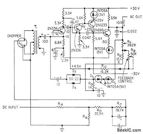
Chopped d-c input is fed to Q2 through T1 and Q1. Base of Q2 is amplifier summing point and receives feedback signals. Gain is 2.73 V rms per volt d-c.-E. R. Schlesinger, Aiming a 3-Ton Telescope Hanging from Balloon, Electronics, 36:6, p 47-51. (View)
View full Circuit Diagram | Comments | Reading(436)
PULSE_PEAK_METER
Published:2009/7/24 1:39:00 Author:Jessie

Indicates peak of fast voltage pulse to within one of several pre determined voltage ranges established by tunnel-diode level-sensing circuit and indicated by series of exclusive-or dual-coil reed relays.-J. C. Rich, Pulse-Peak Indicator, EEE,13:2, p 61. (View)
View full Circuit Diagram | Comments | Reading(541)
BRIDGE_BALANCER
Published:2009/7/24 1:38:00 Author:Jessie

Reference signal from capacitance bridge is transformer-coupled into phase-shifting circuit to compensate for phase shifts in bridge and amplifier used for automatic measurement of dielectric proper ties. Sheet beam tubes V3 and V4 provide gating action for rebalancing servos.-P. G. Frischmann, Measuring Dielectric Properties Automatically, Electronics, 33:32, p 56-57. (View)
View full Circuit Diagram | Comments | Reading(587)
Product_V_F_convertermultiplier
Published:2009/7/24 1:37:00 Author:Jessie

Fig.2-26 This circuit converts the product of two voltages to an equivalent frequency. The 5-kΩ scale-factor trim is adjusted so that the frequency output equals the ratio of V1/V2, as shown by the equations. (View)
View full Circuit Diagram | Comments | Reading(548)
POWER_FREQUENCY_HARMONIC_METER
Published:2009/7/24 1:37:00 Author:Jessie

Has four bandpass filters, tuned to first four harmonics of 60 cps, and vtvm that measures voltage at each filter output, in five ranges covering from 0.3 to 30 v full scale.-. S. Brown, Tuned Voltmeter Reads Harmonic Amplitude, Electronics, 32:3, p 68. (View)
View full Circuit Diagram | Comments | Reading(596)
AIDED_TRACKING_SERVO
Published:2009/7/24 1:37:00 Author:Jessie

Telescope is positioned on remote object by radar and then directed by operator, who adds corrections to tracking vector only if tracking rate changes.-R. L. Schaum and D. W. Savage, Joy-Stick Control Aids Telescope Tracking, Electronics, 32:17, p 87-89. (View)
View full Circuit Diagram | Comments | Reading(537)
SENSITIVE_LOW_COST_
Published:2009/7/2 21:15:00 Author:May

View full Circuit Diagram | Comments | Reading(888)
FASTER_741
Published:2009/7/2 21:14:00 Author:May

Feed-forward techniques extend dynamic response of differential opamp to give unity-gain bandwidth of 18MHz, slew rate over 200 V/μs, and DC gain above 107 V/V while preserving latchup-free operation and wide input voltage range. Composite amplifier uses fast symmetrical four-transistor output stage that is symmetdcally driven by DC-coupled 741 and by AC-coupled feed-forward amplifier, Performance depends on use of nonstandard pin connections for 741. as shown. Developed for processing fast analog data in frequency domain. -J Dostal. 741 + Feedforward =Fast-Differential Op Amp EDN Magazine. Aug 20.1974.p 90. (View)
View full Circuit Diagram | Comments | Reading(923)
TTL_STATE_PROBE
Published:2009/7/2 21:13:00 Author:May
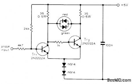
Uses voltage drop of LED in Schmitt trigger to indicate high, low, opencircuit, and pulse-train conditions at probe input. Indicator is Monsanto MV5491 dual redgreen LED package. High input saturates Tr1, cuts off Tr2, and turns on red LED. Low inputcuts off Tr1, and turns on green LED. For high impedance at input, both LEDs are off. Rectangular waves up to about 1 MHz turn on both LEDs, with relative brightness giving rough indication of mark-space ratio.-J. C. Flower, Logic Probe, Wireless World, Sept. 1976, p 72. (View)
View full Circuit Diagram | Comments | Reading(689)
Regulator_with_output_shutdown_on_dropout_battery_low
Published:2009/7/24 2:28:00 Author:Jessie

With this circuit, power is turned completely off when dropout begins (battery low). The circuit will not turn on until (VIN×R2)/( R1+ R2)=2.5 V. This prevents battery creep back from causing oscillation. In some cases, battery voltage will rise temporarily after going low. (View)
View full Circuit Diagram | Comments | Reading(549)
450_MHz_high_gain_amplifier_6_V_supply
Published:2009/7/24 2:28:00 Author:Jessie

The electrical characteristics for the 2N5031/32 shown in this circuit are given in Fig. 2-19B. (View)
View full Circuit Diagram | Comments | Reading(464)
LOW_FREQUENCY_RANDOM_NOISE_GENERATOR
Published:2009/7/24 2:28:00 Author:Jessie

White-noise signals from two sources are filtered, amplified, and fed to symmetrical switching circuit Q4-Q5-T1. On-off switching action of Q4 and Q5 under control of signals gives frequency multiplication required for random output of pulses from about 0 to 5 kc, as required for simulating targets in war games.-R. G. Hundley, Simulating Tactical Radar and Sonar, Electronics, 36:50, p 25-31. (View)
View full Circuit Diagram | Comments | Reading(993)
4_1_2_DIGIT_LCD_DVM
Published:2009/7/2 21:13:00 Author:May

View full Circuit Diagram | Comments | Reading(1538)
_48_V_input_to_5_V_output_zoithout_transformer
Published:2009/7/24 2:28:00 Author:Jessie

Figure 7-56 shows the MAX1771 connected to provide a 5-V output at 300 mA, with a -48-V input. No transformer is required. The conversion efficiency is typically 82%. See Fig. 7-51 for component suppliers. MAXIM NEW RELEASES DATA Book, 1995, P. 4-27. (View)
View full Circuit Diagram | Comments | Reading(715)
SPIRAL_SWEEP_SIMULATOR
Published:2009/7/24 2:27:00 Author:Jessie

Does not require operational radar equipment. Antenna signal is obtained from phase shifter and sweep amplitude potentiometer that provides spiral sweep for target on oscillosope. Range is indicated by gating target to correct radius of spiral sweep. Azimuth is indicated by another gate that limits target appearance to correct angle on spiral sweep.-J. I. Leskinen, Four Ways to Simulate Radar Targets, Electronics, 31 :23, p 82-86. (View)
View full Circuit Diagram | Comments | Reading(571)
450_MHz_high_gain_amplifier_10_V_supply
Published:2009/7/24 2:27:00 Author:Jessie
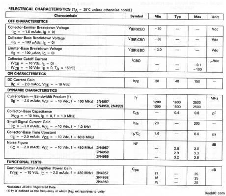
The electrical characteristics for the 2N4957,2N4958,and 2N4959 shown in this circuit are given in Fig.2-18B. (View)
View full Circuit Diagram | Comments | Reading(837)
PULSE_COMMUTATOR_SIMULATOR
Published:2009/7/24 2:27:00 Author:Jessie

Used for checking telemetry ground station equipment without wearing out commutator of telemeter. Magnetic shift register elements are used as ring counters.-J. Porter, Pulse Commutator Simulator Uses Magnetic Logic elements, Electronics, 34:12, p 43-45. (View)
View full Circuit Diagram | Comments | Reading(598)
1_Hz_BANDPASS
Published:2009/7/2 21:13:00 Author:May

Single pot provides easy trimming to exact center frequency desired without change in bandwidth or gain. Q is 10.Design equations are given.-R. A. Pease, Band-Pass Active Filter with Easy Trim for Center Frequency, Teledyne PhilbHck, Dedham, MA, 1972, Applications Bulletin 4. (View)
View full Circuit Diagram | Comments | Reading(733)
1_kHz_BANDPASS_1
Published:2009/7/2 21:11:00 Author:May

Simple circuit using voltage-fonower opamp provbides bandpass of 1 kHz centered on 1 kHz,to give outputrange of 500-1500 Hz.- The Linear and Interface Circuits Data Book for Design Engineers, Texas Instruments, Dallas, TX, 1973, p 4-39. (View)
View full Circuit Diagram | Comments | Reading(558)
1_kHz_BANDPASS
Published:2009/7/2 21:11:00 Author:May
Simple circuit using voltage-fonower opamp provbides bandpass of 1 kHz centered on 1 kHz,to give outputrange of 500-1500 Hz.- The Linear and Interface Circuits Data Book for Design Engineers, Texas Instruments, Dallas, TX, 1973, p 4-39. (View)
View full Circuit Diagram | Comments | Reading(678)
| Pages:1134/2234 At 2011211122112311241125112611271128112911301131113211331134113511361137113811391140Under 20 |
Circuit Categories
power supply circuit
Amplifier Circuit
Basic Circuit
LED and Light Circuit
Sensor Circuit
Signal Processing
Electrical Equipment Circuit
Control Circuit
Remote Control Circuit
A/D-D/A Converter Circuit
Audio Circuit
Measuring and Test Circuit
Communication Circuit
Computer-Related Circuit
555 Circuit
Automotive Circuit
Repairing Circuit