
Signal Processing
Index 152
Treatment for Osteoarthritis (the 2nd)
Published:2011/7/7 9:42:00 Author:Felicity | Keyword: Treatment for Osteoarthritis, the 2nd
Work of the circuit
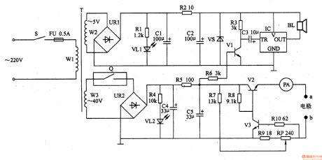
The circuit consists of power supply circuit, constant current output circuit and sound alarm circuit. (It is showed in the picture 9-23.)
Power supply circuit consists of Power switch S, fuse FU, power transformer T, Timers Q, bridge rectifier, URl, UR2, current limiting resistor Rl, R2, R4, R5, light-emitting diode VLl, VL2, filter capacitors Cl, C2, C4, C5 zener diode VS.
Constant current output circuit consists of Resistors R7-RlO, potentiometer RP, transistor V2, V3, PA meter and electrode a, b.
Sound alarm circuit consists of resistors R3, R6, capacitor C3, transistor Vl, music integrated circuit IC and speaker BL. (View)
View full Circuit Diagram | Comments | Reading(452)
Cumulative Timer
Published:2011/7/4 10:20:00 Author:Felicity | Keyword: Cumulative Timer
work of the circuit
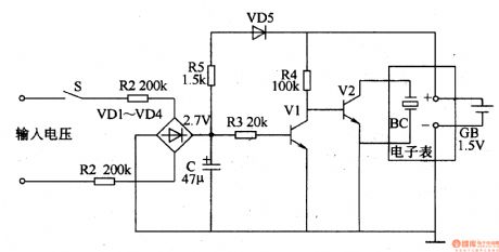
The circuit consists of resistor R1-R4, capacitor C, diode VD1-VD5, transistor V1, V2 and the crystal OSC BC. (It is showed in picture 8-144.)
Turn on the power switch of the electronic instrument and the 220V voltage is limited by R1 and R2 and rectified by VD1-VD4. It produces 2.07V DC voltage on C. The timing begins. When the power switch of the electronic instrument is turned off, the voltage on C disappears. The frequency division circuit stops vibrating. But the frequency division circuit remains in the condition. When you turn on S next time, it begins to time again. (View)
View full Circuit Diagram | Comments | Reading(542)
Ultrasonic Therapeutic Equipment (the 1st)
Published:2011/7/7 9:56:00 Author:Felicity | Keyword: Ultrasonic Therapeutic Equipment, the 1st
Work of the circuit
The circuit consists of power circuit, ultrasonic vibration circuit and outputting circuit. (It showed in picture 9-17.)
Turn on the power switch S and the ultrasonic vibration circuit works. Pulse voltage of 5KV is produced on winding W3 of T. when you use the instrument, use pole A to touch the tissue with focus nidus. The tissue produces sight massage and proper heating to reduce inflammation and ease pain.
Change the value of RP to change the vibration frequency of the ultrasonic therapeutic equipment. (View)
View full Circuit Diagram | Comments | Reading(681)
Magnetism pulse Therapeutic Equipment (the 2nd)
Published:2011/7/7 9:57:00 Author:Felicity | Keyword: Magnetism pulse Therapeutic Equipment, the 2nd
Work of the circuit
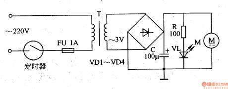
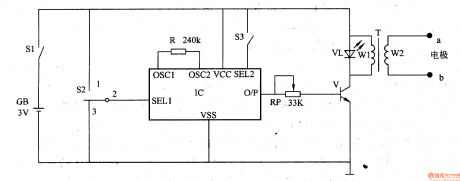
The circuit consists of timer, fusible cut-out FU, mains transformer T, rectifier diodeVD1-VD4, filtering capacitor C, limiting resistor R, power indicating diode VL and motor M. (It is showed in picture 9-16.)
Set the regular time and turn on the power. The 220V AC voltage is adjusted and produces 3v voltage. The DC voltage is M’s working voltage and lightens VL.
When M is working, permanent magnetisms of driver 4 is revolving. It produces moving revolving magnetic field. When you use the equipment, you need to use it to point the treating position.
When the regular time is reached, the switch withen the timer is cut-off. The power of the whole circuit is cut-off and VL stops shines. (View)
View full Circuit Diagram | Comments | Reading(446)
Voltage Regulator (the 1st)
Published:2011/7/7 9:46:00 Author:Felicity | Keyword: Voltage Regulator, the 1st

Work of the circuit
The circuit consists of sampling detection control circuit and relaxation oscillator circuit. (It is showed in picture 7-141.)
Sampling detection control circuit consists of resistors R3-R7, capacitor C5, voltage regulator diode VSI, VS2, diodes and transistors V VDl2.
Relaxation oscillator circuit consists of resistors Rl, R2, capacitor C4, diode VDlO, single-junction transistors VU and isolation transformer T.
Three-phase alternating generator exports pulsating DC voltage +V. The voltage is adjusted by R4 and R5 and added to the negative pole of VS2. The voltage separates into two parts. One is limited by R6 and works as the working voltage of sampling detection control circuit and relaxation oscillator circuit. C4 is charging by R2. When the pressure over C4 reaches the highest value of VU, VU is transmitted. At this time C4 is discharging through VU. When the voltage over C4 is lower than a certain value, C4 begins to charge and discharge. The process repeats and the relaxation oscillator circuit is under the condition of oscillating. The rectifier exports current. (View)
View full Circuit Diagram | Comments | Reading(436)
Electrical Pulse Therapeutic Apparatus (the 12th)
Published:2011/7/7 9:43:00 Author:Felicity | Keyword: Electrical Pulse Therapeutic Apparatus, the 12th

Work of the circuit
The circuit consists of oscillation frequency divider, triangle wave forming circuit, pulse amplifier and booster circuit. (It is showed in the picture 9-12.)
Oscillation frequency divider consists of internal oscillator divider circuit timing IC and capacitor Cl, resistor RlO, Rll, potentiometer RPl.
Triangle wave forming circuit consists of IC and resistors Rl-R8.
Pulse amplifier consists of switch Sl, resistor R9, Rl2, capacitor C2, transistor Vl and working mode selection switch S2.
Booster circuit consists of output amplifier tube V2, step-up transformer T and potentiometer RP.
(View)
View full Circuit Diagram | Comments | Reading(506)
Electrical Pulse Therapeutic Apparatus (the 11th)
Published:2011/7/7 9:44:00 Author:Felicity | Keyword: Electrical Pulse Therapeutic Apparatus, the 11th

Work of the circuit
The circuit consists of power supply circuit, a square wave pulse oscillator, control circuit, pulse peak oscillator and pulse voltage output circuit. (It is showed in the picture 9-11.)
Power supply circuit consists of Source switch Sl, battery GB, filter capacitor C3, current limiting resistor Rll and the power indicator LED VL1.
Square wave pulse oscillator consists of Resistors Rl-R4, capacitor Cl, C2 and transistors Vl, V2.
Control circuit consists of Control switch S2 (S2a, S2b), the transistor V3 and resistors R5-R7.
Pulse peak oscillator consists of resistors R5-R8, capacitor C4, C5, LED V ashamed, diode VD, transistors V4 and pulse transformer T, winding Wl, W2.
Pulse voltage output circuit consists of T’s winding W3, resistors R9, RlO, potentiometer RP, output jack XS, XP and plug electrodes a, b. (View)
View full Circuit Diagram | Comments | Reading(543)
Electrical Pulse Therapeutic Apparatus (the 9th)
Published:2011/7/7 9:44:00 Author:Felicity | Keyword: Electrical Pulse Therapeutic Apparatus, the 9th
Work of the circuit
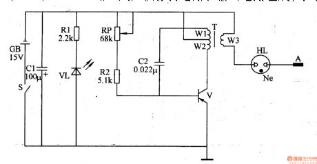
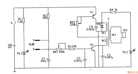
The circuit consists of sound generator and the electrical pulse generator circuit. (It is showed in the picture 9-9.)
Sound generator circuit consists of sound IC IC, resistor R and the control switch S2, S3 components. Electrical pulse generating circuit by the potentiometer RP, transistor V, light-emitting diode VL, step-up transformer T and the electrode a, b.
Change the value of RP to change the Electrical pulse’s stimulus intensity.
You can choose four kinds of sound sources through S2 and S3. They have different effects of electrical stimulation. (View)
View full Circuit Diagram | Comments | Reading(559)
Electrical Pulse Therapeutic Apparatus (the 8th)
Published:2011/7/7 9:45:00 Author:Felicity | Keyword: Electrical Pulse Therapeutic Apparatus, the 8th
Work of the circuit
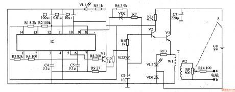
The circuit consists of power supply circuit, self-excited oscillator and electrical pulse generator circuit. (It is showed in the picture 9-8.)
Self-excited oscillator consists of Dual time-base integrated circuit IC, resistors Rl-R4 and capacitors Cl-C5.
Electrical pulse generator circuit consists of transistor Vl-V3, resistors R6-R14, capacitor C6, diode VDl-VD3, light-emitting diode VL2, pulse transformer T, potentiometer RP and electrodes a, b.
Change the value of RP to change the Electrical pulse’s stimulus intensity. (View)
View full Circuit Diagram | Comments | Reading(521)
Electronic Points Probing Instrument (the 2nd)
Published:2011/7/7 9:57:00 Author:Felicity | Keyword: Electronic Points Probing Instrument, the 2nd
Work of the circuit
The circuit consists of probing circuit, OSC, acousto-optic indicating circuit and power circuit. (It is showed in picture 9-39.)
Turn on the switch S. put one pole in the tester’s hand. And use the other one to probe the acupoint near the ears. The 9V voltage of GB makes the OSC work. It also drives HA to make sound. If the electric resistance of the acupoint is small, the frequency of the OSC is higher. The tone of the sound which is made by HA is higher. It works on the other way.
(View)
View full Circuit Diagram | Comments | Reading(467)
Lectronic Weight Instrument (the 1st)
Published:2011/7/7 9:59:00 Author:Felicity | Keyword: lectronic Weight Instrument, the 1st)

Work of the circuit
The circuit consists of power circuit, OSC, pulse-width controlling circuit, pulse group space controlling circuit, paraphase controlling circuit, outputting controlling circuit and driving controlling circuit. (It is showed in picture 9-36.)
Turn on the switch S1 and the 220V DC voltage produces 9V DC voltage. The voltage separates into two parts. One is supplied to outputting circuit. And the other one is stabilized to 5v to work for IC2-IC6. When the OSC is working, oscillation of low frequency is produced from pin 3 of IC3. The internal stimulated switch SO1 and SO3 is turned on with hiatus. The high pressure pulse string is added on the body through pole a, b, c and d.
(View)
View full Circuit Diagram | Comments | Reading(465)
Electronic Pain Relieving Instrument (the 1st)
Published:2011/7/7 10:00:00 Author:Felicity | Keyword: Electronic Pain Relieving Instrument, the 1st

Work of the circuit
The circuit consists of pulse making circuit, controlling circuit and voltage rising circuit. (It is showed in picture 9-31.)
Turn on switch S1 and capacitor is short. Pulse maker makes continues pulse. Then S1 is turned off and the pulse maker makes intermitted pulse.
IC1’s pin 9 outputs pulse signal. The signal is amplified by V1 and V2 and becomes electronic pulse on W2. The electronic pulse stimulates the sexine nurse of skin and makes the cerebrum center make pain relieving hormone. (View)
View full Circuit Diagram | Comments | Reading(482)
Disinfectant Manufacturer (the 1st)
Published:2011/7/7 10:09:00 Author:Felicity | Keyword: Disinfectant Manufacturer, the 1st

Work of the circuit
The disinfectant manufacturer circuit consists of power circuit, timing circuit, controlling circuit, acousto-optic circuit and electrodes. (It is showed in picture 9-92.).
Turn on the power and 220V AC voltage produces +7.5V voltage after being reduced rectified and filtered by T, VD1, VD2 and CI. The voltage then separates into three parts. One is directly supplied on the positive electrode and one is supplied to IC2, electric relay K and annunciator HA while another is supplied to electrode VL.
When the regular time (usually 1 hour) is reached, the annunciator HA will work to remind the users that the disinfectant is done. (View)
View full Circuit Diagram | Comments | Reading(458)
Time Relay (the 1st)
Published:2011/7/7 9:49:00 Author:Felicity | Keyword: Time Relay, the 1st
Work of the circuit
The circuit consists of +12V power circuit, oscillating circuit, delayed trigging circuit and electronic switch circuit. (It is showed in the picture 8-135.)
+12V power circuit consists of resistors Rl-R3, KA relay coil, diode VDl, voltage regulator diode VS and filter capacitor Cl.
Oscillating circuit consists of NAND gate IC IC (Dl-D6) within the non-gate D5, D6 and capacitor C2, resistors R4-R6, potentiometer RPl, diode VD2.
Delayed trigging circuit consists of lC internal NAND gate Dl, D2, D4, resistor Rg, potentiometer RP2, RP3, capacitor C3 and diode VD3.
Electronic switch circuit consists of relay KA, thyristor VT, resistors R7, R8 and capacitor C4. (View)
View full Circuit Diagram | Comments | Reading(771)
Dangerous Area Warning Device (the 3rd)
Published:2011/7/7 9:49:00 Author:Felicity | Keyword: Dangerous Area Warning Device, the 3rd
Work of the circuit
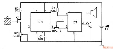
The circuit consists of sensing electrodes A, JFET VF, time-base integrated circuit ICl, language integrated circuit IC2, audio amplification V and speaker BL.(It is showed in the picture 8-123.)
When no one is near to the pole A, the resistance between VF’s drain and source is low. And the value of thee current is large. The level of IC1’s pin 2 is lower than Vcc/3. The alarm does not work.
Change the value of RP1 and RP2 to change the sensitivity of the circuit. If someone is within the distance of 0.5m to the pole, the alarm works. (View)
View full Circuit Diagram | Comments | Reading(460)
Dangerous Area Warning Device (the 1st)
Published:2011/7/7 9:49:00 Author:Felicity | Keyword: Dangerous Area Warning Device, the 1st

Work of the circuit
The circuit consists of regulator circuit, pyroelectric infrared detection trigger circuit, electronic switching circuits, voice circuits, audio power amplifier, low-frequency oscillator and flash drive circuit. (It is showed in the picture 8-121.)
Regulator circuit consist of three-terminal voltage regulator integrated circuit IC2, resistor R3, zener diode VS and filter capacitor Cl, C2.
Pyroelectric infrared detection trigger circuit consists of pyroelectric infrared detection module ICl, transistors Vl, V2, resistors Rl, R2 and potentiometer RP.
Electronic switching circuit consists of electronic switch integrated circuit IC5, resistors R9, RlO and capacitor C8.
Audio power amplifier consists of power amplifier integrated circuit IC4, resistors R6-R8, capacitor C4-C7 and speaker BL.
Low-frequency oscillator consists of Time-base integrated circuit IC6, resistors R11, R12, and capacitor C9, C10.
Flash drive circuit consists of transistor V3, resistors R13-Rl5, field-effect transistors VF1, V F2and light HLl, HL2. (View)
View full Circuit Diagram | Comments | Reading(1401)
temperature detection, voltage-frequency switch circuit
Published:2011/7/9 9:29:00 Author:Lena | Keyword: temperature detection, voltage-frequency switch

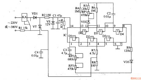
As shown in the figure, the temperature detection, temperature-voltage switch and voltage-frequency switch circuit is used to remote detect temperature. We connect the circuit and wireless transmitting circuit forming a temperature detection remote control transmitting circuit. In the circuit, temperature detection and temperature-voltage switch adopt integrated temperature sensor LM35DZ, this circuit detection temperature range is 0~100℃±O.25℃, linearity span range is 10mV/℃, work voltage range is 4~30V. Voltage-frequency switch circuit adopts special voltage-frequency switch integrated circuit LM131.
(View)
View full Circuit Diagram | Comments | Reading(2650)
Industrial Instrument Used Sound And Light Alarm Two
Published:2011/7/9 6:35:00 Author:Felicity | Keyword: Industrial Instrument, Sound And Light Alarm

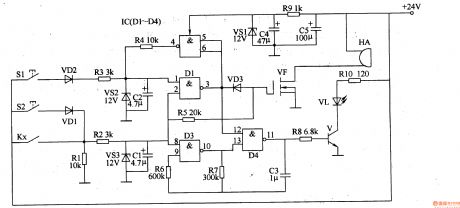
Work of the circuit The circuit consists of + l2V regulator circuit, the switching control circuit, oscillator, bistable trigger circuit and sound and light alarm. (It is showed in picture 8-120.)+ l2V regulator circuit consists of resistors R2, R3, filter capacitor Cl, C5, C6 and regulator diode VS.The switching control circuit consists of resistors Rl, Rl2, mix together goose control VLC and industrial instrumentation control contact (controlled by electrical contacts) Kx.Oscillator consists of NAND gate IC IC (Dl-D5) within the Dl, D2 and the diode VD2, resistors Rll, capacitors C2, C3.Bistable trigger circuit consists of D3-D5 within IC and resistor R7.Sound and light alarm consists of transistor Vl-V3, resistor R4-R6, Rg, RlO, light-emitting diodes VL, diodes VD3, VD4, VD6, field-effect transistors VF, K and alarm relay HA. (View)
View full Circuit Diagram | Comments | Reading(519)
Industrial Instrument Used Sound And Light Alarm One
Published:2011/7/9 6:35:00 Author:Felicity | Keyword: Industrial Instrument, Sound And Light Alarm
Work of the circuit The circuit consists of sound and light alarm circuits, measurement and control circuit, bistable trigger, LED flash circuit, sound the alarm circuit and the + l2V voltage regulator circuit. (It is showed in picture 8-119.)Sound and light alarm circuit consists of industrial instrument control contact (controlled by electrical contacts) K,, resistors Rl, R2, zener diodes VS3and capacitors Cl.Bistable trigger consists of NAND gate IC IC (Dl-D4) within the D3, D4, resistors R6-R8, RlO, capacitor C3, transistor V and light emitting diodes VL.LED flash circuit consists of resistor R5, field-effect transistors VF and alarm HA.Sound the alarm circuit consists of IC internal D1, D2, resistor R3, R4, diode VD2, VD3, voltage regulator diode VS2and capacitor C2. The + 12V voltage regulator circuit Resistor Rg, capacitors C4, C5 and the voltage regulator diode VSl.
(View)
View full Circuit Diagram | Comments | Reading(434)
SAAl293 (TV) single chip microprocessor
Published:2011/7/8 9:26:00 Author:Lena | Keyword: single chip, microprocessor
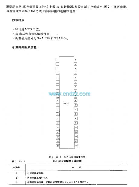


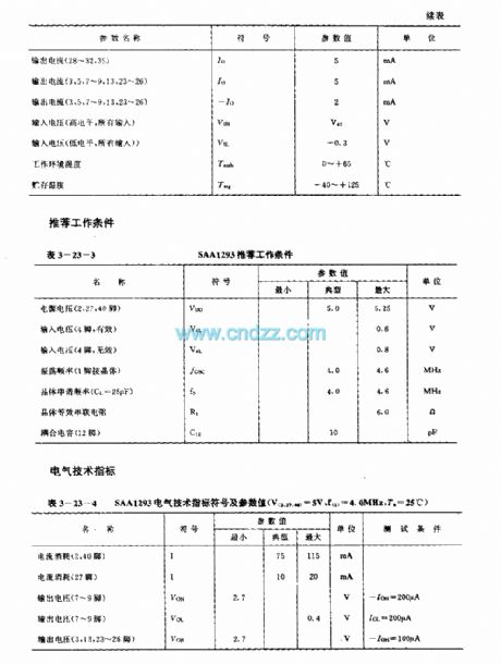
SAA1293 is a single chip microprocessor applied to high/middle TV remote control system. Internal circuit consists of keyboard input and display drive circuit, remote control decoder, clock generator, A/D converter, video and system control output, picture and text driver, coordination signal generator and IM bus line and register interface circuit etc.
Technology characteristicN-channel MOS technics40-pin dual-in-line plastic packageSupporting types are SAA1250 and TBA2800
(View)
View full Circuit Diagram | Comments | Reading(557)
| Pages:152/195 At 20141142143144145146147148149150151152153154155156157158159160Under 20 |
Circuit Categories
power supply circuit
Amplifier Circuit
Basic Circuit
LED and Light Circuit
Sensor Circuit
Signal Processing
Electrical Equipment Circuit
Control Circuit
Remote Control Circuit
A/D-D/A Converter Circuit
Audio Circuit
Measuring and Test Circuit
Communication Circuit
Computer-Related Circuit
555 Circuit
Automotive Circuit
Repairing Circuit