Signal Processing
Industrial Instrument Used Sound And Light Alarm One
Published:2011/7/9 6:35:00 Author:Felicity | Keyword: Industrial Instrument, Sound And Light Alarm | From:SeekIC


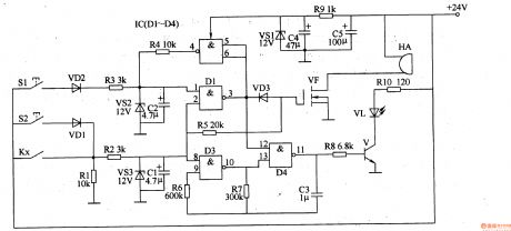
Work of the circuit The circuit consists of sound and light alarm circuits, measurement and control circuit, bistable trigger, LED flash circuit, sound the alarm circuit and the + l2V voltage regulator circuit. (It is showed in picture 8-119.)Sound and light alarm circuit consists of industrial instrument control contact (controlled by electrical contacts) K,, resistors Rl, R2, zener diodes VS3and capacitors Cl.Bistable trigger consists of NAND gate IC IC (Dl-D4) within the D3, D4, resistors R6-R8, RlO, capacitor C3, transistor V and light emitting diodes VL.LED flash circuit consists of resistor R5, field-effect transistors VF and alarm HA.Sound the alarm circuit consists of IC internal D1, D2, resistor R3, R4, diode VD2, VD3, voltage regulator diode VS2and capacitor C2. The + 12V voltage regulator circuit Resistor Rg, capacitors C4, C5 and the voltage regulator diode VSl.
Reprinted Url Of This Article:
http://www.seekic.com/circuit_diagram/Signal_Processing/Industrial_Instrument_Used_Sound_And_Light_Alarm_One.html
Print this Page | Comments | Reading(3)

Article Categories
power supply circuit
Amplifier Circuit
Basic Circuit
LED and Light Circuit
Sensor Circuit
Signal Processing
Electrical Equipment Circuit
Control Circuit
Remote Control Circuit
A/D-D/A Converter Circuit
Audio Circuit
Measuring and Test Circuit
Communication Circuit
Computer-Related Circuit
555 Circuit
Automotive Circuit
Repairing Circuit
Code: