
Signal Processing
Index 147
Supply Camera Cofferdam
Published:2011/7/19 5:58:00 Author:Sue | Keyword: Camera Cofferdam, Diving Equipment, Underwater Photographic Equipment
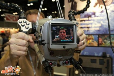

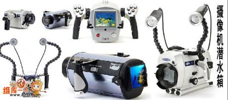
Product Features:
The top viewfinder provides a clear picture of the camera monitor.
It has internal voltage regulator system which is designed for the buoyancy of water.
When the macro lens are touched, the microbe can be amplified doubly.
If there is no light, it will be an effective solution to touch the color correction filter. When the external operating arm is touched, the color correction filter will be indented.
The precise light combined with IR control makes it possible to control the lighting system at your fingertips.
It has waterproof alarm bell with visual and hearing functions.
Option: Suitcase, lighting. (View)
View full Circuit Diagram | Comments | Reading(457)
the textile machine weft feelers
Published:2011/7/22 20:27:00 Author:qqtang | Keyword: textile machine, weft feelers
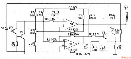
Here is to introduce the textile machine weft feelers circuit which is in the photoelectric control way, it can be the repairing replacement of the of imported injection shuttleless textile machine weft feelers.The working principle of the circuitThe weft feeler consists of the photoelectric signal detection amplifier circuit and LED drive circuit, see as figure 8-133. The photoelectric signal detection amplifier circuit consists of the infrared LED V1 and V2, resistors of R2-R5 and R7-R9, potentiometer RP, capacitor C1 and NI in op-amp circuit IC(N1 and N2).
(View)
View full Circuit Diagram | Comments | Reading(1410)
Receiving Timing Signal Generation Circuit
Published:2011/7/19 8:06:00 Author:Sue | Keyword: Timing, Signal Generation
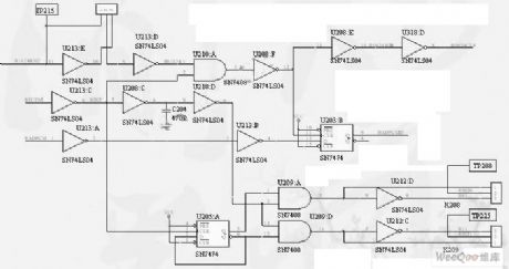
From the figure we can know that similar to transmitting timing signal, the way of timing signal generation is the same, so the waveform is omitted. What should be noted is that, the function of U213:A,B(74LS04), U203:B(74LS74) is to shape and output the received digital baseband signal.
The function of U213:D,E(74LS04), U210:A(74LS08), U208:D,E(74LS08) is to output received clock signal 1024KHz by using the received enable signal(generated by software). (View)
View full Circuit Diagram | Comments | Reading(617)
Bracing Wire Displacement Sensor
Published:2011/7/20 7:08:00 Author:Sue | Keyword: Bracing Wire, Displacement, Sensor

YHL-type displacement sensor will change machine displacement into measurable and electric signal of proportional linearity. When the object has displacement, we can pull the connected steel wire, then the wire will drive the sensor gear to rotate simultaneously with the sensor components. When the displacement is opposite, sensor's internal spring gyroscope will withdraw the coil automatically, and the tension force will remain unchanged during the process. Then electric signals which is directly proportional to the coil's displacement will be output.
The product is small-sized industrial product which is designed on the basis of vibration environment.
(View)
View full Circuit Diagram | Comments | Reading(432)
The fuse box indicator (2)
Published:2011/7/23 21:50:00 Author:qqtang | Keyword: fuse box, indicator

Here is to introduce a fuse box which utilizes the digital display to monitor and indicate the working state of the car fuse box, it characterizes direct display and convenient search.The working principle of the circuitThe fuse box indicator circuit consists of the digital display of integrated circuit type, diode VD, resistor R and power supply switch S, see as figure 7-45.
(View)
View full Circuit Diagram | Comments | Reading(490)
The program controlled filter circuit
Published:2011/7/20 3:07:00 Author:Borg | Keyword: program control, filter circuit
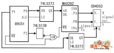
The program controlled filtering is done by MAX262. MAX262 controls the filter through the single chip machine SPI general, of which the central frequency and quality factors are 64-stage and 128-stage programmable and adjustable, respectively, the principle circuit is as shown in the figure.
(View)
View full Circuit Diagram | Comments | Reading(536)
Telephone and facsimile apparatus protection circuit
Published:2011/7/11 2:51:00 Author:Fiona | Keyword: Telephone and facsimile apparatus, protection
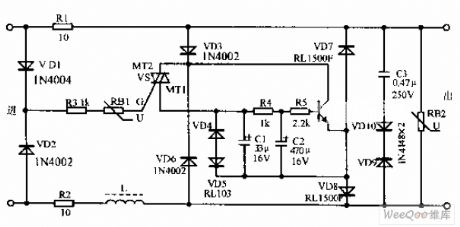
Telephone and facsimile apparatus protection circuit is shown as above,due to the exterior line often appears instantaneous high voltage to result in the damage of the telephone,the facsimile apparatus and so on.In view of this situation,this protection circuit can effectively prevent the damage of the telephone and the facsimile apparatus because of lightning stroke and line's accidental over-voltage.The circuit has no affect on telephone and facsimile apparatus completely. The transistor VD is 9013 and β = 65-115;Directional triode thyristor VS is SAC616;Resistor is the RJ type,nominal power is 0.25 ~ 0.5W on average.
(View)
View full Circuit Diagram | Comments | Reading(633)
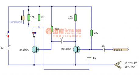
Signal tracing device
Published:2011/7/14 22:26:00 Author:zj | Keyword: Signal tracing
View full Circuit Diagram | Comments | Reading(497)
Single pulse generating circuit
Published:2011/7/19 21:54:00 Author:zj | Keyword: Single pulse
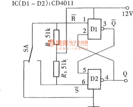
Single pulse could be obtained by a button switch, but due to the button pressing process is easy to produce the chattering phenomenon, and thus which acquired is often not a single pulse, but a group of variable number of pulse series, although some circuits with anti jitter circuit, but for some circuits still can not guarantee its reliability. As shown in the figure the circuit can ensure that each time a button is pressed, you can obtain a pulse, the work is reliable.
(View)
View full Circuit Diagram | Comments | Reading(604)
1 to 9 pulses select circuit (CD4017)
Published:2011/7/19 22:13:00 Author:zj | Keyword: 1 to 9 pulses select
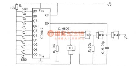
If we want a select multiple pulse, we can adopt the following circuit. You can arbitrarily select pulse in the 1 to 9 range by pressing a button. Its circuit is shown in figure.
(View)
View full Circuit Diagram | Comments | Reading(662)
Frequency shift demodulator(748)composed of active power filter
Published:2011/7/18 22:44:00 Author:zj | Keyword: Frequency shift demodulator, active power filter
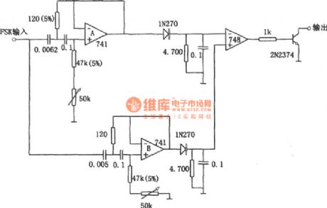
As shown in the figure it is frequency shift demodulator composed of active power filter. Using active power filter instead of LC tuning circuit can makes the frequency shift keying demodulator avoid the use of large and expensive inductors. It not only has the advantagesof small volume, but also improves the performance of demodulation device. The circuit is used for demodulating the 110 bit frequency shift keying signal. Its symbol frequency is 2225Hz. Space frequency is 2025Hz. (View)
View full Circuit Diagram | Comments | Reading(439)
RX3310A receiving module
Published:2011/7/17 22:11:00 Author:zj | Keyword: receiving module
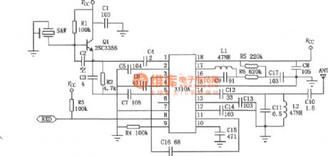
RX3310A module is dedicated to amplitude shift keying modulation of ASK wireless remote control and digital signal receiving module. The module uses a high performance wireless remote control and data transmission for special-purposeintegrated circuit with low noise high frequency amplifier, mixer, local oscillator, amplifier, filter, a comparator, and using 316.8MHz surface acoustic wave resonator, so the work is stable and reliable, suitable for adverse circumstances to work all the time. RX3310A superheterodyne receiver module circuit.
 (View)
View full Circuit Diagram | Comments | Reading(1534)
Orthogonal FM demodulation circuit with CA3098
Published:2011/7/17 22:26:00 Author:zj | Keyword: Orthogonal, FM demodulation circuit
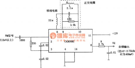
As shown in the figure thecircuit is 10.7MHz LC FM orthogonal demodulation circuit. Integrated circuit CA3089E in the diagram contains positive frequency amplifying circuit. If access ceramic filter ( lumped parameter filter)in the first level, it consists entirely FMdischarge circuit. Limiterworks whenthe input is greater than 12μV. AM differential ratio is 55dB. The output endRC is a de-emphasis circuit. (View)
View full Circuit Diagram | Comments | Reading(985)
Three Waveforms Signal Generator Circuit
Published:2011/7/22 6:23:00 Author:Sue | Keyword: Three Waveforms, Signal Generator
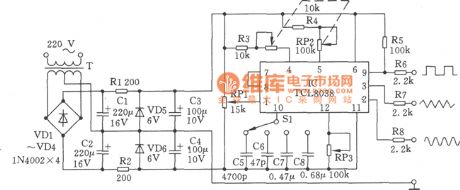
TCL8038 is a kind of special function generation circuit and it has various waveform output function(square wave, triangle wave, sine wave). Its working current is about 10mA with positive and negative power supply. In the figure, C5-C8 use capacitor with small temperature coefficient and small error. When S1 is in C8 block, it can output pulse waveform which is lower than 1Hz. RP2 uses 51-100kΩ double connection linear potentiometer which can facilitate the frequency scale. RP1,RP3 are used to fine-tune the output waveform which can make its up side and down side very smooth. S1 is frequency coarse-tune block. RP2 is frequency fine-tune potentiometer. (View)
View full Circuit Diagram | Comments | Reading(559)
High-low Frequency Signal Generator Circuit
Published:2011/7/22 6:06:00 Author:Sue | Keyword: High-low Frequency, Signal Generator

The high-low frequency signal generator shown in the picture can generate low frequency of 1kHz, intermediate frequency of 465kHz and high frequency of 525-1605 kHz, which will help a lot in repairing and debugging radio or other circuit. It is good for beginners to make. Transistor VT1-VT3 can choose high frequency silicon tube with low power like 3DGI00,3DG201. fT>100MHz. The value of β is between 50 to 100. C7 can use 7/270pF radio with one connection or single connection capacitor of the double connection capacitor. The oscillation transformer T can be reformed on the radio. On the core, we can use 0.08mm high strength enamelled wire to wind L1 100 turns and L2 35 turns. (View)
View full Circuit Diagram | Comments | Reading(1175)
The RC control frequency voltage transformer
Published:2011/7/21 0:41:00 Author:Borg | Keyword: voltage transformer, control frequency
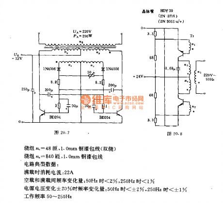
The circuit generates the stable AC voltage with changeable frequency through the multi-resonance oscillator composed of RC circuit, the voltage is output after it is coupled by the transformer. The data of the transformer:
The coil np=40 turns, 2.5mm copper enamelled wire(double turns, internal)
The coil nr=48 turns, 1.0mm copper enamelled wire(double turns)The coil ns=48 turns, 1.0mm copper enamelled wireTypical data of the circuit:The consumed current of full load:22A (View)
View full Circuit Diagram | Comments | Reading(704)
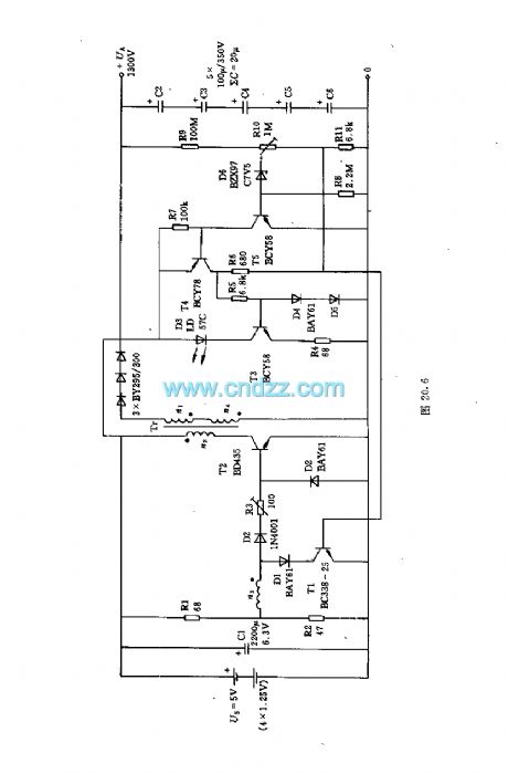
The signal generator of changeable working frequency
Published:2011/7/21 0:30:00 Author:Borg | Keyword: signal generator, working frequency
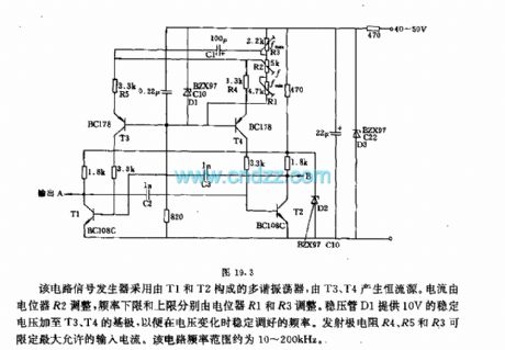
The signal generator consists of the multi-resonance oscillator composed of T1 and T2, the constant current source is generated by T3 and T4. The current is regulated by potentiometer R2, the frequency upper limit and lower limit are regulated by R1 and R3 respectively. The voltage stabilizer D1 provides with a 10V stable voltage for the basic poles of T3 and T4, so the frequency can be regulated when the voltage is changing. The emitter resistors of R4, R5 and R3 can limit the maximum input current. The frequency range of the circuit is about 10~200kHz. (View)
View full Circuit Diagram | Comments | Reading(597)
Voltage Regulator (the 3rd)
Published:2011/7/16 0:37:00 Author:Felicity | Keyword: Voltage Regulator
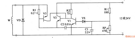
Work of the circuit
The circuit consists of automatic voltage regulation circuit and over-current protection circuit. (It is showed in picture 7-143.)
Automatic voltage regulation circuit consists of Resistors R2, R3, potentiometer RP, capacitor Cl, C2 and Zener diode VS.
Over-current protection circuit consists of Diode VD, resistor R3 and transistor V3.
When the charging voltage of AC electric generator is less than the least value, VS and V1 is cut-off. The charging voltage of AC electric generator is increasing. Here the voltage charges the battery under the certain voltage. When the exporting voltage reaches the highest value, VS is transmitted. The exporting voltage of the motor is decreasing. When the voltage reaches the lowest value, the voltage begins to increase again. In this way, the exporting voltage of the motor is in the scope of 14-14.5 V.
When the working current of V2 is regular, V3 is cut-off. Change the value of RP to change the scope of regulation.
. (View)
View full Circuit Diagram | Comments | Reading(425)
Electrical Pulse Therapeutic Apparatus (the 10th)
Published:2011/7/16 0:39:00 Author:Felicity | Keyword: Electrical Pulse, Therapeutic Apparatus
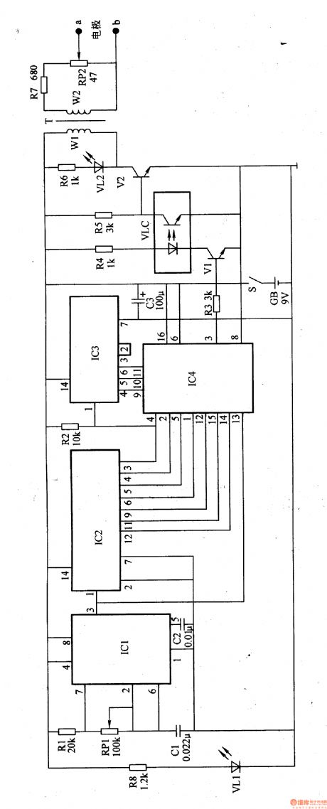
Work of the circuit
The circuit consists of power circuits, low-frequency oscillator, frequency control circuit and pulse voltage generating circuit. (It is showed in the picture 9-10.)
Power circuit consists of Power switch S, batteries GB, filter capacitor C3, limiting resistor R8 and the power indicator LED VLl.
Low-frequency oscillator consists of Resistors Rl, potentiometers RPl, capacitor Cl, C2 and time-base integrated circuit ICl.
Frequency control circuit consists of count divider integrated circuit IC2, 1C3, electronic switch integrated circuit IC4, resistors R3, R4, transistors Vl and optocoupler light emitting diode inside the VLC.
Pulse voltage generating circuit consists of resistors R5-R7, light-emitting diodes VL2, transistor V2, VLC internal photosensitive transistor, the pulse transformer T, and electrode potential R and poles a, b. (View)
View full Circuit Diagram | Comments | Reading(465)
Electrical Pulse Therapeutic Apparatus (the 6th)
Published:2011/7/16 0:38:00 Author:Felicity | Keyword: Electrical Pulse, Therapeutic Apparatus
Work of the circuit
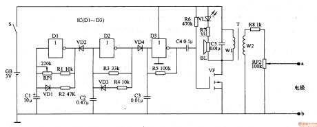
The circuit consists of oscillator A-C and pulse voltage generating circuit. (It is showed in the picture 9-6.)
Oscillator A consists of NAND gate IC IC (Dl-D3) within the non-door Dl, resistor RI, R2, diode VDl, capacitors Cl and potentiometer RPl.
Oscillator B consists of C-NOT gate within the D2, resistor R3, R4, capacitor C2 and diode VD4.
Oscillator C consists of lC internal NAND gate D3, resistor R5 and capacitor C3.
Pulse voltage generating circuit consists of Capacitors C4, C5, resistors R6-R8, light-emitting diode VL, field effect transistors VF, the pulse transformer T, potentiometers RP2 and electrodes a, b.
(View)
View full Circuit Diagram | Comments | Reading(441)
| Pages:147/195 At 20141142143144145146147148149150151152153154155156157158159160Under 20 |
Circuit Categories
power supply circuit
Amplifier Circuit
Basic Circuit
LED and Light Circuit
Sensor Circuit
Signal Processing
Electrical Equipment Circuit
Control Circuit
Remote Control Circuit
A/D-D/A Converter Circuit
Audio Circuit
Measuring and Test Circuit
Communication Circuit
Computer-Related Circuit
555 Circuit
Automotive Circuit
Repairing Circuit