
Signal Processing
Index 151
The turning indicator connection circuit of Santana 2000(gasoline injection engine)
Published:2011/7/12 20:31:00 Author:Borg | Keyword: turning indicator, Santana 2000
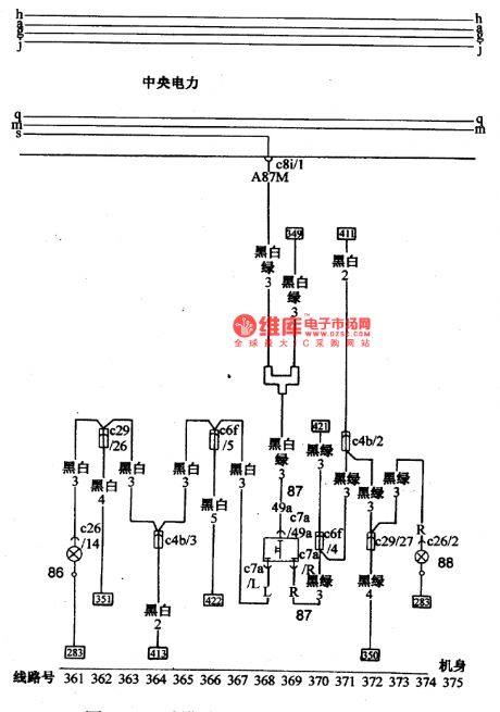
Figure: The turning indicator connection circuit of Santana 2000(gasoline injection engine)86-left turning indicator; 87-turning lamp switch; 88-right turning indicator (View)
View full Circuit Diagram | Comments | Reading(415)
The rear combined lamp wiring circuit of Santana 2000(gasoline injection engine)
Published:2011/7/12 20:27:00 Author:Borg | Keyword: rear combined lamp, gasoline injection engine
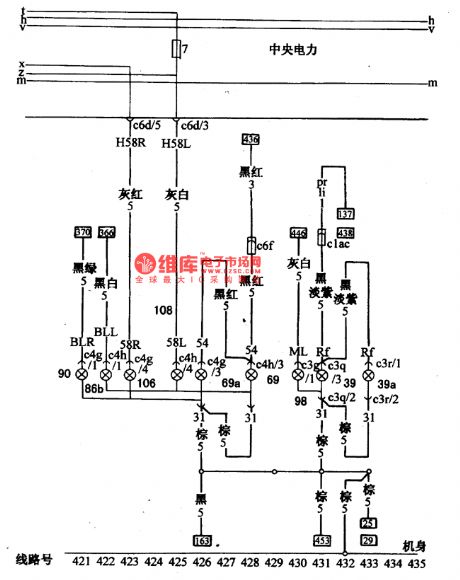
Figure: The rear combined lamp wiring circuit of Santana 2000(gasoline injection engine)39-left backup lamp; 39a-right backup lamp; 69-left brake signal lamp; 69a-right brake signal lamp; 86a-left rear turning signal lamp; 90-right rear turning signal lamp; 106-right tail lamp; 108-left rail lamp; 98-rear fog lamp. (View)
View full Circuit Diagram | Comments | Reading(442)
The fog lamp, back-up lamp and brake lamp switch wiring circuit of Santana 2000(gasoline injection engine)
Published:2011/7/12 20:04:00 Author:Borg | Keyword: fog lamp, back-up lamp, brake lamp switch
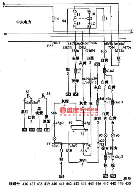
Figure: The fog lamp, back-up lamp and brake lamp switch wiring circuit of Santana 2000(gasoline injection engine)
38-backup lamp switch; 68-brake linked switch; 94-fog lamp relay; 95-left fog lamp; 96-right fog lamp; 97-fog lamp switch; 99-the lighting lamp of fog lamp switch (View)
View full Circuit Diagram | Comments | Reading(657)
The license lamp and instrument lamp wiring circuit of Santana 2000(gasoline injection engine)
Published:2011/7/12 20:27:00 Author:Borg | Keyword: license lamp, instrument lamp
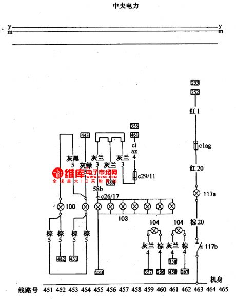
Figure: The license lamp and instrument lamp wiring circuit of Santana 2000(gasoline injection engine)100-license lamp; 103-instrument lighting lamp; 104-ventilation system lighting lamp; 117a-engine under shell lamp; 117a-engine under shell lamp switch. (View)
View full Circuit Diagram | Comments | Reading(432)
The reading lamp and internal lamp wiring circuit of Santana 2000(gasoline injection engine)
Published:2011/7/12 20:28:00 Author:Borg | Keyword: reading lamp, internal lamp, gasoline injection engine
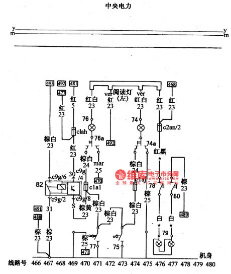
Figure: The reading lamp and internal lamp wiring circuit of Santana 2000(gasoline injection engine)74-reading lamp; 74a-reading lamp switch(right); 75-right door control switch; 76-reading lamp; 76-reading lamp switch (left); 77-left door control switch; 78-sun glasses veil lighting lamp switch (Ⅰ); 78-sun glasses veil lighting lamp; 80-sun glasses veil lighting lamp switch (Ⅱ); 82-internal lamp time relay. (View)
View full Circuit Diagram | Comments | Reading(441)
The trunk lamp and tool case wiring circuit of Santana 2000(gasoline injection engine)
Published:2011/7/12 20:28:00 Author:Borg | Keyword: trunk lamp, wiring circuit
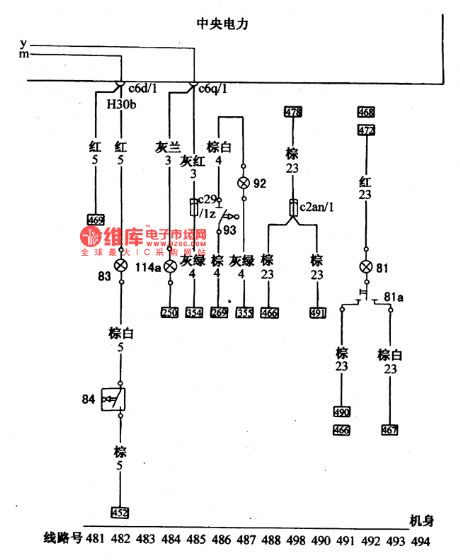
Figure:The trunk lamp and tool case wiring circuit of Santana 2000(gasoline injection engine)81-driving cab lamp; 81a-room lamp switch; 93-trunk lamp; 84-trunk lamp contactor switch; 92-tool chamber lamp; 93-tool chamber lamp switch; 114a-cigarette lighter lamp. (View)
View full Circuit Diagram | Comments | Reading(397)
The head lighting lamp and head turning lamp connection circuit of Santana 2000(gasoline injection engine)
Published:2011/7/12 20:28:00 Author:Borg | Keyword: head lighting lamp, head turning lamp
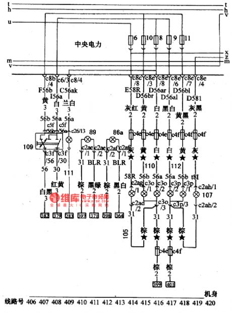
Figure: The head lighting lamp and head turning lamp connection circuit of Santana 2000(gasoline injection engine)86a-left head turning signal lamp; 89-right head turning signal lamp; 105-right head lamp width lamp; 107-left head width lamp; 109-dimming-overtaking lamp switch; 110-right head lighting lamp; 111-high beam indicator; 112-left head lighting lamp (View)
View full Circuit Diagram | Comments | Reading(487)
The ground circuit of Santana 2000(gasoline injection engine)
Published:2011/7/12 20:17:00 Author:Borg | Keyword: ground circuit, gasoline injection engine
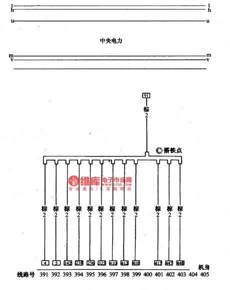
figure: The ground circuit of Santana 2000(gasoline injection engine) (View)
View full Circuit Diagram | Comments | Reading(453)
555 game timer circuit
Published:2011/6/13 23:24:00 Author:nelly | Keyword: Game, timer
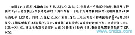
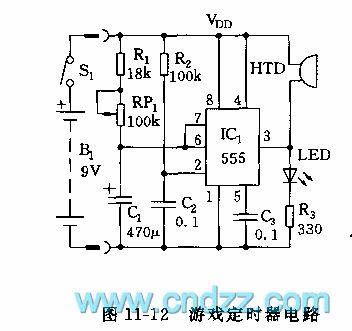
As shown in the figure 11-12, the monostable delay circuit is composed of 555 and R1, RP1, C1, R2, C2. the 2 foot of trigger terminal is connected to the joint point of R2, C2, when it is connected to power supply, the 2 foot has a negative pulse which the level is ground, it can set the circuit, the 3 foot is high level, LED turns on. At the same time, C1 is charged by R1, RP1, when C1's voltage is charged to 2/3 VDD of 6 foot's threshold value level, 555 is reset, the 3 foot is low level, LED turns off, buzzer HTD phonates, it shows that the timing time is reached. The timing time td=1.1(R1+RP1)C1. The td of indicative parameter is adjustable in the range of 10s~60s, it can be previously set according to the needs of game.
(View)
View full Circuit Diagram | Comments | Reading(662)
555 disconnection photoelectric isolation protecting circuit
Published:2011/6/13 23:25:00 Author:nelly | Keyword: disconnection, photoelectric isolation
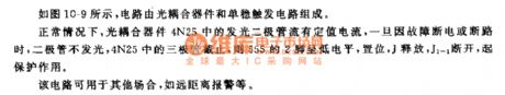
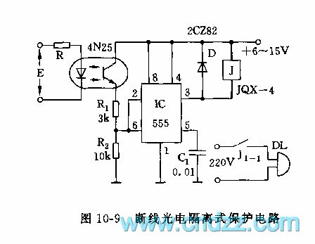
As shown on the figure 10-9, the circuit consists of the CCD and monostable trigger circuit. Gernerally, the CCD 4N25's LED has a current ration. Once it is power-off by some faults, the diode will not light and the 4N25's will be cut off, the 555's 2 foot will be low power level. Then the J will release and the J1-1 will turn off to protect the circuit. This circuit can be used in other occasions, such as distant warning.
(View)
View full Circuit Diagram | Comments | Reading(1405)
Three terminals capacitor applied circuit diagram
Published:2011/6/14 7:22:00 Author:Sophia | Keyword: Three terminals capacitor, 10DB
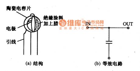
High pass filter of high-frequency circuit usually adopts ceramic capacitor. in the practical designing, the selection of capacitance is very important, the function is different according to the different frequency. so the high pass filter should be designed according to eleminating high freguency noise and reduceing the unneccesary radiation quantity. The high pass filter can get excellent performance by using the Three terminals capacitor .
The structure and equivalent circuit of Three terminals capacitors is showed as the below chart. The electrode of the capacitor connects the U lead, and the anode of the capacitor is the input and output end. When working, the U lead connects the mainsside and the terminals for power supplies of the opposite lead near the electronic device connects human. If the connection is good, the attenuation performance can improve to 10dB.
(View)
View full Circuit Diagram | Comments | Reading(598)
Power supply, starting, igniting, instrumentation, signal basic circuit diagram of Beijing
Published:2011/7/7 4:30:00 Author:Sophia | Keyword: Power supply, starting, igniting, instrumentation, signal basic circuit, Beijing
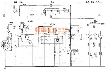
1. Ignition switch
Ignition switch 7 is JR424-type. It is used to connect or disconnect the starter, ignition and electrical lines, and it has four locations: 0 position (off position): The key can only be inserted into or set aside in this position. I position (power position): After starting the engine, It connects the ignition circuit to maintain the normal operation position. Ⅱ position (starting position): This position is to start the engine, when hands is loosened. The key will be automatically returned to power position I. Ⅲ position (attachment position): the engine is not running, the cassette players and other appliances need to be used. The ignition switch will be transfered to this position.
2. Distributor
Distributor9 is FDl3 type, direction of rotation is counter-clockwise direction. firing interval is 90 ° -1 °, the adjustment angle of octane number is 12 °, the contact clearance is 0.35 -0 · 5mm. breaker arm spring pressure is 4.9-6 · 86N; the maximum speed of continuous firing (in the distributor shaft calculated) is 2300r/min, the maximum centrifugal advance angle is 10 ° -13 °, the engine ignition sequence is 1-2-4-3, capacitors is DR203A-type, 12V, 0.20 -0 · 25μF.
3 ignition coil Ignition coil 8 is DQO7A type or DQ148 type. Primary voltage is l2V, secondary voltage is 150OOV more.When wind motoris running, warm air flows from defrost mouth.
(View)
View full Circuit Diagram | Comments | Reading(532)
Quartz Crystal Oscillation Circuit of C-MOS Converter
Published:2011/6/14 13:07:00 Author:Michel | Keyword: C-MOS Converter, Quartz Crystal, Oscillation Circuit
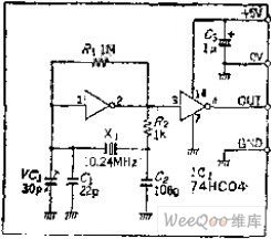
Circuit's Functions Recently,there is a trend that people changes C-MOS for TTL devices.What's more,74HC-series products also got further enrichment.The oscillating circuit composed of C-MOS IC can substitute for clock oscillating circuit composed of level two TTL because TTL IC stops oscillating and causes abnormity easily.However,this circuit is simple with accurate oscillation.
Circuit's Work PrincipleThe partial resistor R1 is connected between input and output ends and make the input end fix on threshold voltage to keep C-MOS changeover job in online linear status. (View)
View full Circuit Diagram | Comments | Reading(543)
Low Distortion and State Variable Two-phase Oscillation Circuit
Published:2011/6/14 13:15:00 Author:Michel | Keyword: Low Distortion, State Variable, Two-phase Oscillation Circuit

Circuit's Functions
The amplifier used in audio equipments needs low distortion signal when it tests.Recently,there are many low distortion OP amplifiers used in audio equipments.If oscillator has distortion, the measurement will be restricted.The state variable circuit has some parts of the active power filter and it can change into oscillators if positive feedback is added.The integrator is composed of two-stage opposite phase amplifier and the high frequency distortion caused by integrator itself reduces 6DB/OCT per stage.This circuit is adopted in low distortion oscillating circuit and if the difference valuefor input and output phase of integrator is 90 degree,it will get 2 phase oscillation output. (View)
View full Circuit Diagram | Comments | Reading(1785)
Simplified Infrared Remote Control Receiving Circuit by Using Monolithic IC
Published:2011/6/14 13:13:00 Author:Michel | Keyword: Monolithic IC, Infrared Remote Control, Receiving Circuit
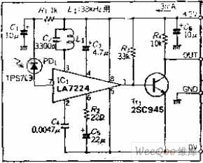
Circuit's Functions Infrared remote control is widely used in audio and video equipments.This circuit adopts LA7224 and it intergrates the preamplifier,peak keeping circuit, integral circuit etc. in a chip and these devices are used receive signal,which simplfies the circuit.
Circuit's Work Principle It removes silicon light diode to receive infrared radiation via current.Because the signal is very weak,60DB need be amplified.To improve S/N,the carrier wave is taken out by usingresonant tank composed of L1 and C2 and it keeps the peak via limiting circuit. C4 is integral capacitance, according to manufacturer requirements, capacity chooses 0.0047 UF. (View)
View full Circuit Diagram | Comments | Reading(507)
Ungoverned Quartz Crystal Oscillating Circuit without Inductance L
Published:2011/6/14 21:20:00 Author:Michel | Keyword: Ungoverned Quartz Crystal, Oscillating Circuit
Circuit's Functions
If the transistor's collector load adopts LC resonance loop and the oscillation frequency of Pierce C - B or Boer, B - E circuit must attuned a little deflective to make the oscillation stable.This oscillating circuit can be used if there is no inductance L.
Circuit's Work Principle
If quartz resonator is used as inductance L,it can be used as deformation carat diop oscillating circuit.Capacitor C2 and C3 feedback posistively and the frequency is low and electric capacity is large.
The oscillation frequency reaches 5~20MHZ when capacity is 100PF and a proper capacity can be chosen according to requirements. (View)
View full Circuit Diagram | Comments | Reading(554)
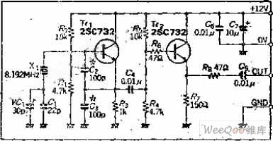
Dual TV and radio signal generator
Published:2011/7/6 5:00:00 Author:Lucas | Keyword: Dual , TV , radio , signal generator

The signal generator circuit shown in the chart is simple and easy to make. This signal generator can be used as launching grid television image test signal and medium wave band radio test signals. Component selection: RC components, transistor . The specific data is shown as the chart. The power source uses a NO.5 battery, Sl is 2 × 2 small DPDT switch, and S2, S3 are the ordinary small switches . L3 is made by Φ1.5mm silver-plated copper wire winded with 4 turns, and in the the tap of the first turn, the hollow coil diameter is 1 cm.
(View)
View full Circuit Diagram | Comments | Reading(1106)
Internal telephone circuit
Published:2011/7/1 5:53:00 Author:Fiona | Keyword: Internal telephone

Internal telephone circuit is shown as below,improving slightly a toy telephone will become a variable practical internal telephone. This phone is compose of the phone component,decoding circuit,ringing circuit and other components. Using more than two the same device parameters telephone connected by wire can constitute internal telephone.
(View)
View full Circuit Diagram | Comments | Reading(2101)
Waveform generator made by single chip
Published:2011/7/10 23:26:00 Author:leo | Keyword: Waveform generator, single chip

As the picture shows, it is a waveform generator made by MCS-51 single chip. It has the features of simple circuit, compact construction and low price. It can produce triangle waveform, sawtooth waveform, sine waveform, square waveform and others. These six kinds of waveform can be connected to each other and constant cyclically output or be one of them can be selected out to output constantly. If key controller and LED displayer are set to it, the square wave output frequency can be set and shown by changing the software. (View)
View full Circuit Diagram | Comments | Reading(741)
Treatment for Osteoarthritis (the 1st)
Published:2011/7/7 9:43:00 Author:Felicity | Keyword: Treatment for Osteoarthritis, the 1st
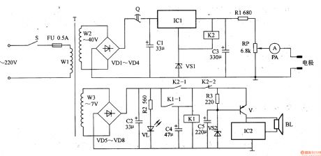
Work of the circuit
The circuit consists of power supply circuit, timing circuit, current regulation circuit, control circuit and music alarm circuit. (It is showed in the picture 9-22.)
Power supply circuit consists of power switch s, the power transformer T, rectifier diode VDl-VD8, filter capacitor Cl, an integrated three-terminal regulator ICl and voltage regulator diode VS1.
Timing circuit consists of mechanical timer Q.
Current regulation circuit consists of relay K1 and K2.
Control circuit consists of Potentiometer RP and ammeter PA.
Music alarm circuit consists of Music integrated circuit IC2, the transistor V, and the speaker BL. (View)
View full Circuit Diagram | Comments | Reading(802)
| Pages:151/195 At 20141142143144145146147148149150151152153154155156157158159160Under 20 |
Circuit Categories
power supply circuit
Amplifier Circuit
Basic Circuit
LED and Light Circuit
Sensor Circuit
Signal Processing
Electrical Equipment Circuit
Control Circuit
Remote Control Circuit
A/D-D/A Converter Circuit
Audio Circuit
Measuring and Test Circuit
Communication Circuit
Computer-Related Circuit
555 Circuit
Automotive Circuit
Repairing Circuit