
Signal Processing
Index 149
The igniting system and power supply parameter circuit of Santana 2000 (32MP003182)
Published:2011/7/15 19:19:00 Author:Borg | Keyword: igniting system, power supply parameter
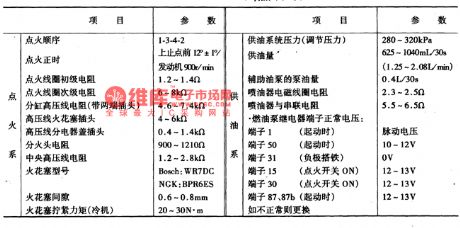
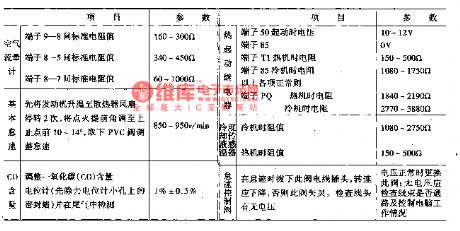
The way to test the engine electric control unit is to use the multimeter with high impedance, so the control unit won't be broken due to the parallel connection with elements in test. When the test is done, the power supply should be cut off, the igniting switch should be shut down, and the voltage and the LEV should be tested with the according voltage gear of the multimeter. To avoid breaking or loosing the computer connector terminal, a test box(equipment V.A.G1598 and cable V.A.G1598-9) is used to detect it, the terminal numbers are corresponding to the computer connector terminals.
(View)
View full Circuit Diagram | Comments | Reading(474)
Electromagnetic therapeutic apparatus (1)
Published:2011/7/20 1:19:00 Author:TaoXi | Keyword: Electromagnetic, therapeutic, apparatus

The principle of the circuit
The electromagnetic therapeutic apparatus circuit is composed of the power switch S1, the electromagnetic coils L1 and L2, the rectifier diodes VD1-VD5, the LED VL, the resistors Rl-R4, the potentiometer RP, the thyristor VT, the two-way trigger diode V, the capacitors C1-C3 and the constant magnetic/pulse selector switch S1, the circuit is as shown in figure 9-13.
Components selection
The R1-R4 use the 1/4W metal film resistor.The RP uses the organic solid potentiometer.The C1 and C2 use the 400V CBB capacitor or the polyester capacitor; C3 uses the 5OV aluminum electrolytic capacitor.The VD1-VD4 use the 5A, 400V silicon rectifier diode; VD5 uses the 1N4007 silicon rectifier diode.
(View)
View full Circuit Diagram | Comments | Reading(704)
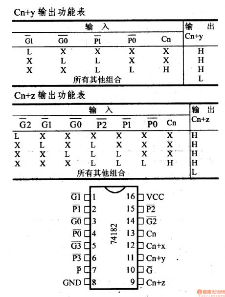
74 series digital circuit 74182, 74S182 advanced carry generator
Published:2011/7/19 1:47:00 Author:TaoXi | Keyword: 74 series, digital circuit, advanced, carry, generator
View full Circuit Diagram | Comments | Reading(1308)
Linear voltage-controlled oscillator(8038、μA741) circuit
Published:2011/7/20 23:31:00 Author:leo | Keyword: Linear oscillator, voltage-controlling

As the picture shows, it is a linear voltage-controlled oscillator circuit. A1 is the constant current power supply circuit used to improve C1, which ensure the linear relationship between output frequency and input controlled voltage. A2 is the sine wave output bumper. If inputting low frequency saw wave to the voltage controlled port, the circuit is changed to linear scan generator and if inputting the voltage of some signal into input port, the circuit outputs frequency-modulated wave.
(View)
View full Circuit Diagram | Comments | Reading(2490)
74 series digital circuit 74181, 74LS181 arithmetic logic units/function generators
Published:2011/7/19 2:40:00 Author:TaoXi | Keyword: 74 series, digital circuit, arithmetic, logic, unit, function generator
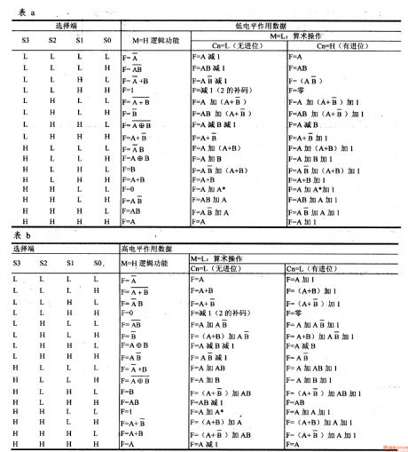
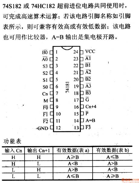
When the 74S182 or 74HC182 is used with the advanced carry circuit, it can complete the high-speed arithmetic; if this circuit's pin names are as shown in the pin table, it can compatible with the high or low effective data; this circuit can be used as the comparator, the A=B output is the collector electrode's open circuit.
(View)
View full Circuit Diagram | Comments | Reading(6848)
74 series digital circuit 74221 dual monostable multivibrator (with the Schmidt trigger)
Published:2011/7/15 4:50:00 Author:TaoXi | Keyword: 74 series, digital circuit, dual, monostable, multivibrator, Schmidt trigger
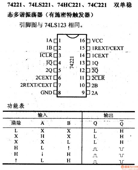
74221, 74LS221, 74HC221 and 74C221 dual monostable multivibrators (with the Schmidt trigger)
(View)
View full Circuit Diagram | Comments | Reading(2069)
The function generator circuit formed by 555 timer
Published:2011/7/20 23:21:00 Author:leo | Keyword: Function generator, timer

As the picture shows, it is a function generator circuit formed by 555 timer. This circuit is made up of a CH7555 timer, some transistors and RC components, which can generates triangle wave, square wave, sine wave, saw wave and swept wave. All kinds of wave have a adjustable frequency from 0.1 Hz to 100k Hz. The amplitude of vibration of square wave is from 5 V to 15 V which can drive TTL circuit. The accuracy of sine wave is higher than 3%.
(View)
View full Circuit Diagram | Comments | Reading(1881)
VHF-band FM Circuit of Variable Capacitance Diode
Published:2011/7/13 8:06:00 Author:Michel | Keyword: VHF-band, FM Circuit

Circuit's Functions
The frequency modulation FM transmitter which can be used in 76~90MHZ FM radio band, usually also it is called wireless microphone.It adopts signals via FM radio receiver.The signals can be transmitted in wireless means if we don't use the microphone but input low frequency signals.The transmitting distance can reach over 30 meters if the 60CM antenna is used.
Circuit's Work PrincipleThe TT1 makes the signal generated by the electret capacitor microphone amplify to diode's work voltage.80MHZfrequency band signal is generated by LC oscillation circuit and it is showed as the picture.The Oscillation chart L's strcture:The lead is winded to the reel with magnetic core and the oscillation frequency alters among 6~90MHZ by adjusting magnetic core. (View)
View full Circuit Diagram | Comments | Reading(2188)
Soft Start Control Signal Generation Circuit
Published:2011/7/11 7:42:00 Author:Michel | Keyword: Soft Start Control, Signal Generation Circuit

Thispiture is soft start control signal generating circuit . This circuit can be used as output voltage of power supply which is used to decrease soft start control signal and motor rotation rate control signal source of small mechanical impact. Constant output of current diodes VD5 charges and discharges C1,which gains a linear increase/decrease waveform.A1 and A2 choose small input bias current FET input type operational amplifier,NJMO82BD. The linear rise signal of the circuit is compared with the triangle waveform via comparator and it forms PWM signal.If the soft start signal is gained by changing the PWM signal dutyfactor slowly.Operational amplifiers also can choose general LF412 and AD712 etc. (View)
View full Circuit Diagram | Comments | Reading(760)
The Multi-purpose signal generator circuit
Published:2011/7/14 22:16:00 Author:TaoXi | Keyword: Multi-purpose, signal generator

The multi-purpose signal generator circuit is composed of the integrated circuit oscillators and the frequency dividers, it produces the square wave from the high frequency to the sub-audio frequency, and it also produces the frequency standard VHF. The alternative oscillator part feeds the signal back to the 10-frequency divider stage. The extra SN7490 frequency divider can connect into the points of the frequency divider to add the 5 frequency division and 2 frequency division functions. The light-emitting diode of the 1MHz crystal stage indicates that whether the circuit is oscillating. The second stage can use any external crystal, the operating frequency is in the VHF low frequency range.
(View)
View full Circuit Diagram | Comments | Reading(1382)
555 audio equipment turn-on and turn-off
Published:2011/7/11 23:08:00 Author:TaoXi | Keyword: 555, audio equipment, turn-on, turn-off,
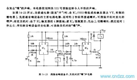
When you are tuning on or tuning off the audio equipment, the audio equipment circuit has the process from the temporary stabilization state to the stabilization state, so the speaker will send out the sound of pu , this circuit can eliminate this sound by using two pieces of 555.
As the figure 14-23 shows, when the power supply turns on, the trigger which is composed of the IC1(555) and the relay J1 which is controlled by VT1 are connected to the main circuit power of the audio equipment, the delay time is about 2 seconds and then connect the speaker, so the sound of pu when you are tuning on the equipment is eliminated; when you are tuning off the equipment, because the pin-4 of the trigger IC2 is connected with the ground, so the IC2 resets, and it firstly cuts off the speaker through J2, the delay time is about 1 second, then it cuts off the main power of the audio equipment, so the sound of pu is eliminated.
(View)
View full Circuit Diagram | Comments | Reading(524)
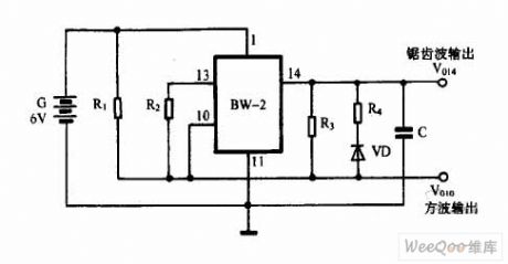
Signal Generator Circuit of BW-2
Published:2011/7/13 7:19:00 Author:Michel | Keyword: Signal Generator, Circuit
View full Circuit Diagram | Comments | Reading(489)
PLL FM demodulator(LM565CN\RC4558DN)
Published:2011/7/20 2:50:00 Author:zj | Keyword: PLL, FM demodulator

As the diagram shows it adopts LM565CN which consists of 10kHZ±3kHz FM demodulation circuit. The V1 and V2 differential demodulation outputarelevel shiftedand amplificatedby differential amplifier ofA1 in figure b. Thenthe 20kHz pulsating component is filtered by the active LPF composed of A2. (View)
View full Circuit Diagram | Comments | Reading(1484)
ICL7135(or 5G7135) typical application
Published:2011/7/20 2:50:00 Author:zj | Keyword: typical application

View full Circuit Diagram | Comments | Reading(7185)
Saw k6265(K) 38MHZ surface acoustic wave filter
Published:2011/7/20 2:51:00 Author:zj | Keyword: 38MHZ surface, acoustic wave filter

View full Circuit Diagram | Comments | Reading(656)
High voltage pulse generator circuit
Published:2011/5/11 8:52:00 Author:Nicole | Keyword: pulse generator

The figure is as shown, it uses 6V~12V DC power supply to produce a high voltage pulse. The oscillator is composed of triode Q1, Q2, it will produce a 3Hz DC pulse voltage, and it is imported a primary coil with 6V:240V, when the pulse is ended, it will produce a high voltage on the primary coil of transformer. The repetition rate of pulse depends on C2, R1. This circuit is used for truncheon, it can adopt lead-acid battery. (View)
View full Circuit Diagram | Comments | Reading(5148)
Vienna bridge sinusoidal oscillator circuit
Published:2011/7/17 1:26:00 Author:Fiona | Keyword: sinusoidal oscillator

View full Circuit Diagram | Comments | Reading(1016)
High frequency sine wave generator and orthogonal output circuit
Published:2011/7/17 1:23:00 Author:Fiona | Keyword: High frequency, sine wave generator, orthogonal output

View full Circuit Diagram | Comments | Reading(3630)
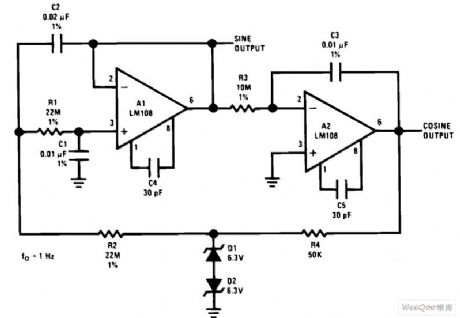
Low frequency sine wave generator and orthogonal output circuit
Published:2011/7/17 1:22:00 Author:Fiona | Keyword: Low frequency, sine wave generator, orthogonal output
View full Circuit Diagram | Comments | Reading(3515)
Sensor Structure Circuit
Published:2011/7/17 9:48:00 Author:Robert | Keyword: Sensor, Structure

The picture shows the sensor structure circuit. (View)
View full Circuit Diagram | Comments | Reading(511)
| Pages:149/195 At 20141142143144145146147148149150151152153154155156157158159160Under 20 |
Circuit Categories
power supply circuit
Amplifier Circuit
Basic Circuit
LED and Light Circuit
Sensor Circuit
Signal Processing
Electrical Equipment Circuit
Control Circuit
Remote Control Circuit
A/D-D/A Converter Circuit
Audio Circuit
Measuring and Test Circuit
Communication Circuit
Computer-Related Circuit
555 Circuit
Automotive Circuit
Repairing Circuit