
Signal Processing
Index 145
SIGNAL_GENERATOR
Published:2009/6/17 22:08:00 Author:May

Useful for troubleshooting audio, video, and lower frequency RF amplifiers, this circuit gener-ates a signal that is rich in harmonics. (View)
View full Circuit Diagram | Comments | Reading(0)
DELAYED_PULSE_GENERATOR
Published:2009/6/17 21:47:00 Author:May


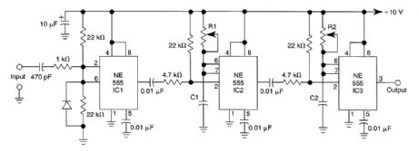
Three 555 IC timers are used in this circuit to construct a simple delayed-pulse generator. IC1 acts as a waveform shaper to produce a rectangular waveform. IC2 produces a delaying pulse to trig-ger IC3 on the trailing edge of the delaying pulse. R1 controls delay time and R2 controls pulse width. As much as a 10:1 range can be generated.Delay: C1= 1.1 x 10⁻⁵ T delay c μFPulse: C2 = 1.1 x 10⁻⁵ T pulse T μsec (View)
View full Circuit Diagram | Comments | Reading(5)
DIGITALLY_CONTROLLED_SAWTOOTH_PULSE_GENERATOR
Published:2009/6/17 21:29:00 Author:May
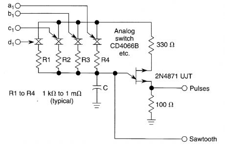
Use of an analog switch as shown allows digital control of a UJT oscillator. (View)
View full Circuit Diagram | Comments | Reading(513)
PULSE_GENERATOR
Published:2009/6/17 21:21:00 Author:May

By using a 556 dual timer with IC1A acting as a waveshaper and IC1B as a pulse generator, a 10:1 range of pulse widths can be generated.A sine wave can be used to trigger this circuit. (View)
View full Circuit Diagram | Comments | Reading(2669)
ADD_ON_PULSE_GENERATOR
Published:2009/6/17 21:20:00 Author:May

This pulse generator can supplement a standalone pulse generator. Using a transistor and a 555 Limer, pulse widths of <5 μs to 500 μs can be produced. The value of C3 is approximately found from Lhe formula:C3μF ≈ 1.1 x 10⁻⁵T whereT is the shortest pulse width (μs) desired in a 10:1 range(T should be greater than 5 μs)The capacitor values and consequent pulse width range are shown. (View)
View full Circuit Diagram | Comments | Reading(611)
ELECTROMAGNETIC_RING_LAUNCHER
Published:2009/6/17 3:40:00 Author:May

The electromagnetic ring launcher is comprised of four subcircuits: a clock circuit (built around U5, a 555 oscillator/timer configured for astable operation), a count-down/display circuit (built around U3), a 74190 synchronous up/down counter with BCD outputs that is configured for countdown operation; U4, a ECG8368 BCD-to-7-segment latch/decoder/display driver; and DISP1, a commnon-cathode seven-segment display), a trigger circuit (comprised of U6), an MOC3010 optoisolator/coupler with Triac-driver output; TRI, an SK3665 200-PIV, 4-A Triac; and a few support components), and a reset circuit (comprised of U1, a 7400 quad 2-input NAND gate; U2, a second 555 os-cillator/timer configured for monostable operation; and a few support components).
This circuit is that of a repulsion coil (L1) used to demonstrate the principle of electromagnetic repulsion by propelling a metal ring around the core of L1 through the air. A countdown circuit is provided to count seconds before launch. (View)
View full Circuit Diagram | Comments | Reading(5708)
SECOND_ORDER_POLYNOMIAL_GENERATOR
Published:2009/6/17 3:26:00 Author:May


By using a circuit built with a single analog multiplier and five precision resistors, an output volt-age (Vo) can be made to create a second-order polynomial.The circuit implements the following quadratic:
VO=a+bVx+cV 2X
The input terminals of IC1 are connected to create a positive square term and present the Vx signal to the output with a 1-10-V scale factor, Incorporating the voltage-divider network (resistors R3 and R4) in the input signal path provides additional attenuation adjustment for the coefficient (c) of the square term in the quadratic. Then, the passive adder (resistors R1, R2, and RO) is wired to IC1's internal summing circuit to generate the polynomial's other two terms; the offset term (a) and the linear coefficient (b). (View)
View full Circuit Diagram | Comments | Reading(958)
TRIANGLE_AND_SQUARE_WAVE_GENERATOR
Published:2009/6/17 3:12:00 Author:May

The circuit will generate precision triangle and square waves. The output amplitude of the square wave is set by the output swing of op amp A1, and R1/R2 sets the triangle amplitude. The frequency of oscillation in either case is approximately 1/0.69RC.The square wave will maintain 50% duty cycle-even if the amplitude of the oscillation is not symmetrical. The use of a fast op amp in this circuit will allow good square waves to be generated to quite high frequencies. Because the amplifier runs open-loop, corapensation is not necessary. The triangle-generating amplifier should be a compensated type. A dual op amp, such as the MC1458, can be used for most applications. (View)
View full Circuit Diagram | Comments | Reading(1657)
CLOCK_DRIVEN_TRIANGLE_WAVE_GENERATOR
Published:2009/6/17 3:08:00 Author:May

U2-a, C3 and R2 operate as an integrator. Q2 and Q3 are alternately switched at 256 cycles. U2-b, Q4, Q5, and R8 through R11 are a constant current generator, and R11 is set for a symmetrical triangular waveform. (View)
View full Circuit Diagram | Comments | Reading(927)
SINGLE_TRANSISTOR_CODE_PRACTICE_OSCILLATOR
Published:2009/6/17 3:01:00 Author:May

A 2N366 is configured as an audio feedback oscillator using an audio transformer is shown. Adjust R1 for proper operation and desired audio note. (View)
View full Circuit Diagram | Comments | Reading(2153)
VARIABLE_FREQUENCY_CODE_PRACTICE_OSCILLATOR
Published:2009/6/17 2:59:00 Author:May

The variable frequency audio oscillator can be used as a low-level alarm sounder or a codepractice oscillator. (View)
View full Circuit Diagram | Comments | Reading(950)
TRIANGLE_WAVE_OSCILLATOR
Published:2009/6/17 2:57:00 Author:May

U1-b acts as an integrator while U1-a is a threshold detector. R2 sets the trip level and therefore the amplitude. R3 controls charging current of C1 and the frequency. (View)
View full Circuit Diagram | Comments | Reading(1512)
LINEAR_SAWTOOTH_GENERATOR
Published:2009/6/17 2:52:00 Author:May

The 2N3906 transistor is used as a constant-current source, to assure that the 555-based sawLooth generator generates a linear ramp waveform. (View)
View full Circuit Diagram | Comments | Reading(2033)
CODE_PRACTICE_OSCILLATOR
Published:2009/6/17 2:48:00 Author:May

The tone and volume of the sound produced when the telegraph key is depressed can be varied in this code practice oscillator. (View)
View full Circuit Diagram | Comments | Reading(2)
SIGNAL_GENERATOR
Published:2009/6/17 2:48:00 Author:May

This simple oscillator is rich in harmonics which make this circuit useful for signal tracing applications. (View)
View full Circuit Diagram | Comments | Reading(144)
MORSE_PRACTICE_OSCILLATOR
Published:2009/6/17 2:47:00 Author:May

A 555 timer configured as an astable multivibrator is used in this circuit to generate an audio note. C1 can be changed to vary the audio note as desired. (View)
View full Circuit Diagram | Comments | Reading(1010)
TRIGGERED_SAWTOOTH_GENERATOR
Published:2009/6/17 2:46:00 Author:May

Two 2N3904 transistors and a 555 form a triggered sawtooth generator. A sawtooth or other rising voltage input provides a pulse output when the trigger point is reached. (View)
View full Circuit Diagram | Comments | Reading(1800)
QRP_SIDETONE_GENERATOR_CODE_PRACTICE_OSCILLATOR
Published:2009/6/17 2:44:00 Author:May

For use with low-power transmitters with a positive keying voltage. Q1/Q2/Q3 form a switching amplifier. When the key is pressed, the collector of Q3 goes to ground, tuming on Q5 and activating IC1, an audio oscillator. Q4 drives the speaker. For use as a code practice oscillator, insert P1 and J1 and a key in J2. (View)
View full Circuit Diagram | Comments | Reading(821)
LIGHT_CONTROLLED_OSCILLATOR
Published:2009/6/17 2:42:00 Author:May

This circuit can be used as a light detector and possibly as an aid for the visually handi-capped. The frequency of the oscillator is deter-mined by the amount of illumination striking LDR4. (View)
View full Circuit Diagram | Comments | Reading(669)
TRIANGLE_WAVE_GENERATOR
Published:2009/6/17 2:41:00 Author:May

This is a simple triangle-wave generator using two IC devices and a transistor. The triangle wave is used as feedback to the square-wave generator. S1 allows range switching in three ranges from 100 Hz to 100 kHz. Extra positions could be used to extend the range to lower frequencies, using larger values of capacitance. (View)
View full Circuit Diagram | Comments | Reading(3751)
| Pages:145/195 At 20141142143144145146147148149150151152153154155156157158159160Under 20 |
Circuit Categories
power supply circuit
Amplifier Circuit
Basic Circuit
LED and Light Circuit
Sensor Circuit
Signal Processing
Electrical Equipment Circuit
Control Circuit
Remote Control Circuit
A/D-D/A Converter Circuit
Audio Circuit
Measuring and Test Circuit
Communication Circuit
Computer-Related Circuit
555 Circuit
Automotive Circuit
Repairing Circuit