
Signal Processing
Index 153
oscillating circuit and trigger circuit diagram
Published:2011/6/18 21:19:00 Author:Lena | Keyword: oscillating circuit, trigger circuit
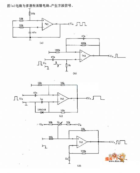
Diagram (a) circuit is a multivibrator type oscillating circuit which can generate Square-Wave signal.
(View)
View full Circuit Diagram | Comments | Reading(484)
70MHz Paralleled Crystal Oscillator Circuit
Published:2011/6/30 4:18:00 Author:Joyce | Keyword: 70MHz , Paralleled, Crystal Oscillator
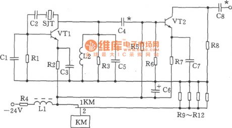
As shown in the figure is the 70MHz paralleled crystal oscillator circuit. The oscillator is mainly composed of transistor VT1, crystal SJT ,capacitance C1、 C5 and other components.
Choices of components:
Capacitance C1 is 20p, C2 is 100p, C3, C7 is 820p, C4 is 56p, C5, C8 is 47p, and C6 is 47u F / 50V. Inductance DLL for μ22 H (color code inductance), L2 is 0.3 μH. Resistance R1 is 1.6 kΩ ,R2 is
1kΩ, R3 is 750Ω and R4 is 180Ω,1W, R5 is 1.3 Ω , R6 is 3kΩ ,R7 is 360Ω, R8 is 470 Ω, R9 ~ R12 is 300Ω, 2W . Choices for transistor VT1, VT2 could be 3DG828 ,65≤β≤115. Crystal SJT could use model JA98-70MHz. Relays KM is JUC - 1M. (View)
View full Circuit Diagram | Comments | Reading(582)
48MHz HCMOS Oscillator Circuit
Published:2011/6/30 4:17:00 Author:Joyce | Keyword: 48MHz , HCMOS , Oscillator
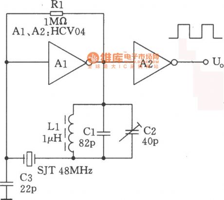
As shown in the figure is a 48MHz crystal oscillator composed of HCMOS integrated circuit. The fundamental frequency of the crystal is 16MHz, but the oscillator is compelled to work on triple frequency harmonic. The importance of harmonic oscillator is to inhibit the fundamental frequency of the crystal. The parallel resonant circuit in the graph will resonate on the basis of the fundamental frequency of the crystal, when it is connected with crystal and SJT in series, the impedance to the fundamental frequency will be the highest, thus it can effectively refrain the fundamental frequency from oscillation and ensure the oscillation of the triple frequency harmonic. (View)
View full Circuit Diagram | Comments | Reading(713)
56~512kHz High-frequency Oscillator Circuit
Published:2011/6/30 4:17:00 Author:Joyce | Keyword: 56~512kHz, High-frequency , Oscillator
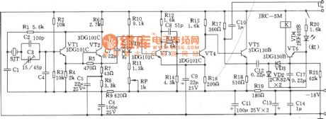

As shown in the figure is 56 ~ 512 kHz high-frequency oscillator circuit. It consists of high frequency oscillators and an alarm circuit.
1. The technique data:
(1) Frequency range: 56 ~ 512 kHz;
(2) output level: + 5.5± 1dB;
(3) frequency accuracy: no more than ± 20Hz;
(4) Alarm signal: when it stops oscillating, the alarm will light send out an alarm call.
(5) working temperature: it can guarantee index between 0 to + 45 ℃, and work reliably between - 10 to 0 ℃ and + 45 to + 50 ℃
Choice of components :
audion VTl~VT4:3DG101C、β=65 ~ 85, VT5 ~ VT6:3DG1308, β= 85 ~ 115. Quartz crystal SJT: 101 quartz crystal with foot stand t namely GZC7 - F. Choices for capacitor C1 and C4 are shown in the table attached.
(View)
View full Circuit Diagram | Comments | Reading(596)
Seat Belt Language Reminder
Published:2011/7/10 22:46:00 Author:Felicity | Keyword: Seat Belt, Language Reminder

Work of the circuit
The circuit consists of Power regulator / indicator circuit, control circuit, the language generator and audio amplifier output circuit. (It is showed in picture 7-114.)
Power regulator / indicator circuit consists of current limiting resistors R2, R5, zener diode VS and LED HL.
Control circuit consists of Ignition switch S1, turn-on switch S3 and turn-off switch S2.
The language generator consists of language IC lCl, resistors Rl, R3 and capacitor Cl, C2.
Audio amplifier output circuit consists of audio power amplifier IC lC2, resistor R4, capacitor C4, C5 and speaker BL. (View)
View full Circuit Diagram | Comments | Reading(1327)
Sleepiness Reminder
Published:2011/7/10 23:41:00 Author:Felicity | Keyword: Sleepiness Reminder
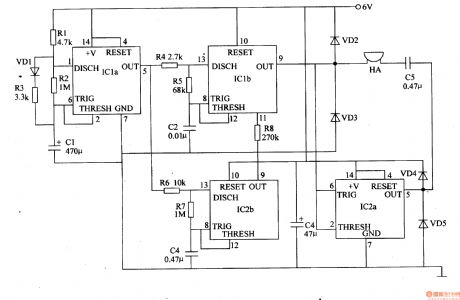
Work of the circuit
The circuit consists of astable oscillator, lkHz oscillator, 3Hz ultra-low-frequency oscillator and the audio output circuit. (It is showed in picture 7-117.)
Astable oscillator consists of dual time-base integrated circuit ICla, resistors Rl-R3, diodes VDl and capacitors CI.
lkHz oscillator consists of IClb, resistors R4, R5 and capacitor C2.
3Hz ultra-low-frequency oscillator consists of dual time-base integrated circuit IC2b, resistors R6, R7 and capacitor C4.
The audio output circuit consists of IC2a, diode VD2-VD5, capacitor C5 and buzzer HA. (View)
View full Circuit Diagram | Comments | Reading(607)
Ultra-low-frequency Infrared Therapeutic Instrument
Published:2011/7/10 23:04:00 Author:Felicity | Keyword: Ultra-low-frequency Infrared, Therapeutic Instrument,
Work of the circuit
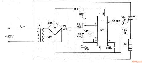
The circuit consists of power circuits, ultra-low frequency oscillator and control circuit. (It is showed in picture 9-29.)
Power circuits consists of power switch S, the power transformer T, bridge rectifier, UR, filter capacitors Cl and three-terminal voltage regulator integrated circuit IC1.
Ultra-low frequency oscillator consists of resistors Rl, R2, potentiometer RP, diodes VDl, capacitors C2, C3 in a timely manner based integrated circuit IC2.
Control circuit consists of Resistor R3, LED VL, thyristor VT and diode VD2. (View)
View full Circuit Diagram | Comments | Reading(917)
Health Therapeutic Instrument
Published:2011/7/10 22:55:00 Author:Felicity | Keyword: Health, Therapeutic Instrument,
Work of the circuit
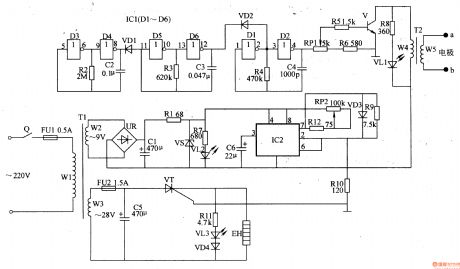
The circuit consists of power supply circuit, electrical pulse generator circuit and magnetic thermal control circuit. (It is showed in picture 9-30.)
Power supply circuit consists of timer Q, fuse FUl, FU2, power transformer Tl, bridge rectifier, UR, filter capacitor Cl, C5, voltage regulator diode VS, current limiting resistor Rl, R7, and power indicator LED VLl.
Electrical pulse generator circuit consists of six non-gate integrated circuit ICl (Dl-D6), resistors R2-R6, R8, potentiometer RPl, capacitors C2-C4, diode VDl, VD2, transistors V and pulse transformer T2.
Magnetic thermal control circuit consists of time-base integrated circuit lC2, resistors R9-Rl2, potentiometer RP2, capacitor C6, diode VD3, VD4, light-emitting diodes VL3, thyristor VT and electric heater EH.
(View)
View full Circuit Diagram | Comments | Reading(1017)
The crossbar user extension outside metering device circuit
Published:2011/7/7 7:22:00 Author:Fiona | Keyword: The crossbar user, extension outside metering device

The crossbar user extension outside metering device circuit is shown as above,this device is suitable for HJ-905, HJ-906-type extension outside metering device that the the crossbar user switchboard. The metering device has a easy circuit, low cost and easy maintenance features.As the counting device is for each extension units,for convenience of copy times,it equips with 4-digit electromagnetic counter,it's eye-catching visual. The metering device is composed of pulse shaping,pulse string of gap detection, the first 0 discrimination, pulse string of records, timing and counting circuit and other circuit.
(View)
View full Circuit Diagram | Comments | Reading(981)
series attenuation test circuit
Published:2011/7/8 4:13:00 Author:Fiona | Keyword: attenuation test

Compared with the transmission attenuation measurement circuit,series attenuation test circuit adds two pole-throw switch K4,K5.
(View)
View full Circuit Diagram | Comments | Reading(677)
Telephone anti-theft trick lock circuit
Published:2011/7/8 10:36:00 Author:Fiona | Keyword: anti-theft trick lock

Telephone anti-theft trick lock circuit is shown as above, this lock's specific functions as follows: 1.1~4 any limited prefix numbers, such as 0 , 173 , 9688 , can lock 1000 groups. 2.4 * password,confidentiality is strong.3.it can change the password and limited number at any time.4.* it delays about 6S to automatically shut after call to prevent free call on limited number. 5 Setting the password and limited number are operated on telephone.6.When the outside line is parallel operation theft,it makes a alarm sound to disturb the theft phone, while the red light is bright.7.The green light is bright when the users calling,it says the line is busy. Circuit is divided into limited local dial-up and parallel operation thief dozen two completely independent parts.
(View)
View full Circuit Diagram | Comments | Reading(681)
Telephone electronic ringer circuit
Published:2011/7/8 11:24:00 Author:Fiona | Keyword: electronic ringer

Telephone electronic ringer circuit is shown as above,Figure (a) is the electronic ring circuit with an NPN transistor V1 (choose 9014 or 3DG12) as the core, sound devices YD is also feedback devices composed of the feedback pole and the buzzer equipped with the help of the sound chamber. L1, L2 connect to circuit line;C1 and R1 have limiting and reducting voltage effects; R2 is the isolation resistor.D1 is the commutation diode.DW is the clamper tube. Figure (b) is the electronic ringing circuit with A general CMOS integrated block CD4069(or 4069, MC4069, TC4069)as the core design.
(View)
View full Circuit Diagram | Comments | Reading(2417)
Lost Reminder
Published:2011/7/10 22:12:00 Author:Felicity | Keyword: Lost Reminder

Work of the circuit
The circuit consists of power circuit, trigger control circuit and voice circuits. (It is showed in picture 7-116.)
Power circuit consists of battery GB, diode VDl, filter capacitor C2, C4, C5 and the voltage regulator integrated circuit ICl.
The trigger control circuit consists of door switch SI, door light EL, the diode VD2, resistors Rl-R3, capacitor Cl, transistors Vl, V2, and pomegranate combined optical device VLC.
Voice circuit consists of microphone BM, recording switch S2, voice integrated circuit IC2, capacitor C3, C6, resistors R4, R5 and speaker BL. (View)
View full Circuit Diagram | Comments | Reading(735)
Telephone diacritical transponder circuit
Published:2011/7/9 2:55:00 Author:Fiona | Keyword: diacritical transponder

Telephone diacritical transponder circuit is shown as above,the diacritical transponder increases diacritical speaker function for the telephone and keeps secret for identity of the person who answers the phone.Diacritical integrated circuit TM0071A (or KTS00T1A) is New single piece of large-scale speech processing integrated circuit and dual in-line 16-pin package,the voltage range is 3 ~ 5V, the power supply can be obtained after the telephone power supply maintains the voltage.When installing,it removes the transmitter MIC of theoriginal telephone,connects the MIC input terminal of the output connection phone and power supply side to telephone power supply,all components can be mounted on a small circuit board.The circuit board can be put in the phone's leisure place.Function conversion can use a micro switch which is fixed on the phone shell.
(View)
View full Circuit Diagram | Comments | Reading(807)
Telphone convenient lamp circuit
Published:2011/7/9 2:31:00 Author:Fiona | Keyword: convenient lamp

Telephone convenient lamp circuit is shown as above,S is the tact switch connected with microphone key,it is off at ordinary times, it is connected in off-hook status.HA is piezoelectric ceramic chip which is pasted in the speaker YD,L1 and L2 are the telephone lines.When it has no ringing signal or it isn't in off-hook state,3 terminal of NE555 is low potential,relay J does not work,and when it has a ringing signal or it is in off-hook state, J is conducted to make K close and H light.it is thus clear that the convenient lamp provides timely lighting when you receive and make a call at night.
(View)
View full Circuit Diagram | Comments | Reading(531)
Phone number coded lock circuit
Published:2011/7/9 0:38:00 Author:Fiona | Keyword: number coded lock

Phone number coded lock circuit is shown as above,this picture is the specific application circuit of digital password integrated blocks BA9101,it is composed of keyboard,multi-functional dial-up integrated network circuit,peripheral control circuit and so on.This coded lock has a major, minor secondary control,it is suitable for three kinds of use levels and can respectively control according parameters.Keeping password and parameters is supplied by the lithium battery,it is not lost in five years.
(View)
View full Circuit Diagram | Comments | Reading(991)
Telephone hands-free circuit
Published:2011/7/9 0:23:00 Author:Fiona | Keyword: hands-free

Telephone hands-free circuit is shown as above, this picture is HA22 (VI) P/TD type telephone hands-free circuit produced by jiangsu.When the telephone is in h-f state,the receiver is replaced by speaker; The microphone is replaced by sound power converter(the pickup) BM. hands-free circuit is composed of IC1, IC2 six transistor (9013) and so on. When the switch CH5 and CH6 are linked together,hands-free indicator VD7 is bright, the telephone enters into the h-f state, when CH5,CH4 are linked together or off-hook, the hands-free circuit is closed.
(View)
View full Circuit Diagram | Comments | Reading(1977)
Ultrasonic Drilling Machine Two
Published:2011/7/7 2:39:00 Author:Felicity | Keyword: Ultrasonic Drilling Machine

Work of the circuit The circuit consists of power supply circuit, ultrasonic oscillator circuit, pre-amplifier, amplifier and power amplifier drive output circuit. (It is showed in picture 8-125.)Power supply circuit consists of power switch Sl, fuse FU, power transformer m, bridge rectifier, URl and UR2, capacitors C9 and Cll-C13, resistors R16 and R17, voltage regulator diode VS, three-terminal integrated circuit IC and the power light steady HL.Utrasonic oscillator circuit consists of resistors Rl-R4, transistor Vl, Cl-C4 capacitors and inductors L.Pre-amplifier consists of transistor Vl-V5, resistors R5-Rl5, potentiometer RP, capacitors C5-C8 and ClO, and the input transformer Tl.Amplifier consists of Input transformer Tl, T2 and transistor coupling transformer V6, V7.Power amplifier drive output circuit consists of transistor V8-Vll, resistors Rl9-R22, diode VDl-VD4, the control switch S2, ammeter PA, output transformer and transducer B. (View)
View full Circuit Diagram | Comments | Reading(2818)
Ultrasonic Drilling Machine One
Published:2011/7/7 2:37:00 Author:Felicity | Keyword: Ultrasonic Drilling Machine

Work of the circuit The circuit consists of power supply circuit, ultrasonic oscillator, driver amplifier and power output circuit. (It is showed in picture 8-124.)Power supply circuit consists of power switch S, the power transformer Tl, rectifier diode VDl-VD8, ammeter PA, resistor R8, three-terminal voltage regulator integrated circuit IC and filter capacitors Cl, C3, C5, C6.Ultrasonic oscillator consists of resistor R9, Rll, Rl2, inductor L, capacitor C7-C9 and transistor V7.Driver amplifier consists of capacitor C4, transistors V8 and V9, n and the input transformer resistor R7, RlO, R13, R14. Power output circuit consists of input transformer M’s windings W2 and W3, power amplifier tube Vl-V6, resistors Rl-R6, the output transformer T3, cap acitor C2 and ultrasonic transducer B
(View)
View full Circuit Diagram | Comments | Reading(2294)
60-nary counter circuit
Published:2011/7/6 9:09:00 Author:John | Keyword: counter

View full Circuit Diagram | Comments | Reading(471)
| Pages:153/195 At 20141142143144145146147148149150151152153154155156157158159160Under 20 |
Circuit Categories
power supply circuit
Amplifier Circuit
Basic Circuit
LED and Light Circuit
Sensor Circuit
Signal Processing
Electrical Equipment Circuit
Control Circuit
Remote Control Circuit
A/D-D/A Converter Circuit
Audio Circuit
Measuring and Test Circuit
Communication Circuit
Computer-Related Circuit
555 Circuit
Automotive Circuit
Repairing Circuit