Signal Processing
70MHz Paralleled Crystal Oscillator Circuit
Published:2011/6/30 4:18:00 Author:Joyce | Keyword: 70MHz , Paralleled, Crystal Oscillator | From:SeekIC

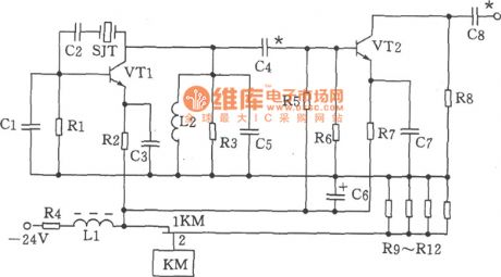
As shown in the figure is the 70MHz paralleled crystal oscillator circuit. The oscillator is mainly composed of transistor VT1, crystal SJT ,capacitance C1、 C5 and other components.
Choices of components:
Capacitance C1 is 20p, C2 is 100p, C3, C7 is 820p, C4 is 56p, C5, C8 is 47p, and C6 is 47u F / 50V. Inductance DLL for μ22 H (color code inductance), L2 is 0.3 μH. Resistance R1 is 1.6 kΩ ,R2 is
1kΩ, R3 is 750Ω and R4 is 180Ω,1W, R5 is 1.3 Ω , R6 is 3kΩ ,R7 is 360Ω, R8 is 470 Ω, R9 ~ R12 is 300Ω, 2W . Choices for transistor VT1, VT2 could be 3DG828 ,65≤β≤115. Crystal SJT could use model JA98-70MHz. Relays KM is JUC - 1M.
Reprinted Url Of This Article:
http://www.seekic.com/circuit_diagram/Signal_Processing/70MHz_Paralleled_Crystal_Oscillator_Circuit.html
Print this Page | Comments | Reading(3)

Article Categories
power supply circuit
Amplifier Circuit
Basic Circuit
LED and Light Circuit
Sensor Circuit
Signal Processing
Electrical Equipment Circuit
Control Circuit
Remote Control Circuit
A/D-D/A Converter Circuit
Audio Circuit
Measuring and Test Circuit
Communication Circuit
Computer-Related Circuit
555 Circuit
Automotive Circuit
Repairing Circuit
Code: