
Signal Processing
Index 150
Pulse shaping circuit composed of gate circuit(CD4069)
Published:2011/5/17 4:00:00 Author:Ecco | Keyword: Pulse shaping circuit , gate circuit
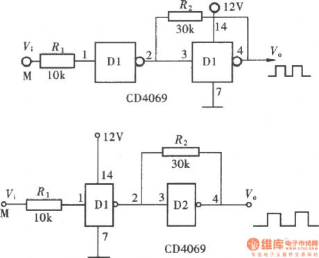
As CMOS gate having a fixed threshold level, the part lower than the threshold of the signal pulse has no responding to the input end of gate circuit. Using this feature, it can be directly used in the pulse shaping. In practical electronic circuits, integrated gate circuit is one of the most practical one. It's used as a control gate, also used to form the clock pulse generator. As an integrated gate circuit often contains several independent gates, so there are always some spare parts besides the main structure of the circuits. And they can use these extra parts to make the pulse shaping, RP, amplifier and so on. For some high demanding circuits, the direct use of plastic gate can not meet the requirements, but it will form a Schmitt trigger gate, the using of Schmitt trigger hysteresis make the pulse shaping circuits meet the requirements, this structure of the circuit is shown as the chart. (View)
View full Circuit Diagram | Comments | Reading(1418)
50Hz high-precision time base signal source(CD4060)
Published:2011/5/12 2:24:00 Author:Ecco | Keyword: 50Hz , high-precision , time base, signal source

In some of the early production of the digital electronic clocks with AC power supply, the 50Hz AC power frequency is used as a second time base after fractional frequency because of structure. As the frequency of AC power will always has a certain bias, this small deviation will cause the large deviation between the real time and clock over time. In order to eliminate this bias, amateur enthusiasts make a variety of 50Hz high-precision time base circuits. The most using is the circuit composed of CD4060, it is shown as the chart.
(View)
View full Circuit Diagram | Comments | Reading(5564)
Frequency signal tracking circuit (PLL circuit) composed of CD4046
Published:2011/5/12 2:16:00 Author:Ecco | Keyword: Frequency signal , tracking , PLL

Frequency signal tracking circuit is the phase-locked loop circuit, which is one of the basic application circuit of CD4046. The circuit shown as the chart and composed of CD4046 is a PLL circuit, and it can capture and track the input signal with the input frequency in l00~100kHz . (View)
View full Circuit Diagram | Comments | Reading(6745)
Ten blocks frequency signal generator(CD4011、CD4017)
Published:2011/5/12 2:05:00 Author:Ecco | Keyword: Ten blocks, frequency, signal generator

Usually, we use the general-purpose frequency signal generator which is designed as the entire frequency range with a continuous adjustment approach. However, in actual use, we only use a few test frequency. Here the frequency signal generator has been designed ten commonly used fixed-frequency gears,and you can choose the gear according to the need. The frequency signal generator consists of digital gear selector switch and ten fixed frequency signal generator, it is shown as the chart.
(View)
View full Circuit Diagram | Comments | Reading(1463)
Transistor ringing current generator
Published:2011/5/12 2:07:00 Author:Ecco | Keyword: Transistor, ringing current generator

Transistorringing current generatorchanges 24V DC into 60 ~ 90V AC ringing voltage for the supply of communications equipment, such as carrier, high-frequency terminals, wired telephone. 1. Technical performance (1) Input power: DC 24V ± 10%; (2) Rated output: 60 ~ 90V AC; (3) Frequency: 20Hz ± 5Hz; (4) Working conditions: temperature +5 ℃ ~ +40 ℃, ≤ 80% relative humidity environment, it can continuous work in 24 hours. 2. Choosing components: Cl, C2 use 1000μ/50V capacitor, C3 uses 200μ/50V capacitor, C4 is 10μ/150V capacitor. Resistor Rl is 200Ω, 1/2W, R2 is 1kΩ, lW, R3 is 3.6kΩ, 2W, R4 is 5.1kΩ, lW, R5 is 20kΩ, 1W, all of them are metal film resistors. Potentiometer RP is 33Ω, lW. Zener VDl is 2CW75, VD2 is 2CW73. Diode VD3, VD4 are 2CPl3. Transistor VTl is 3AD638, VT2, VT3 are 3AD30C. HL lights is XDX-24V, 0.5A, neon uses NH0-4C (60V, lmA). Power switch SA is KN3-3 (DPDT). Insurance FU is BGXP-1 2A fusion tube. Transformer T uses silicon material with core cross-sectional area in 38 × 45mm2. Nl, N4 are Φ0.25mm 39 high-strength magnet wires with winding turns, N2, N3 use enameled high strength Φ0.49mm with l89 turn, they are two-lane and winding. N5 uses enameled Φ0.35mm high strength wire with 840 turns.
(View)
View full Circuit Diagram | Comments | Reading(771)
Low frequency oscillator (flashing shine circuit) circuit 1 made by 555 time-base circuit
Published:2011/5/12 2:03:00 Author:Ecco | Keyword: Low frequency, oscillator, flashing, shine , 555, time-base circuit

The chart shows a flashing shine circuit, and when the circuit works, twolight-emitting diodes will shine simultaneously. The working principle of the circuit is similar to 555 audio oscillator, the difference is that the capacity of capacitor Clis increased to 4.7μF. Therefore, the circuit's oscillation frequency is very low, the changing rate of potential on pin 3 of NE555 is low. When the output of pin 3is inhigh level, the light-emitting diode VDl, VD2 are lit at the same time. When the output of pin 3is inlow level, the light-emitting diode VDl, VD2 turns off.In the circuit, when the resistance of R3 is higher, the brightnessis smaller; or resistance of R3 is lower, the brightnessis greater. Note:theresistance of R3 should not be too small, otherwise the current flowing through the light-emitting diodes is too high, the power consumption is higher,it will have negative impact on thelight-emitting diode, or even it is burned. Typically, the current flowing through the LED can be controlled between 10 ~ 20mA.
(View)
View full Circuit Diagram | Comments | Reading(980)
Low frequency oscillator (flashing shine circuit) circuit 2 made by 555 time-base circuit
Published:2011/5/12 2:01:00 Author:Ecco | Keyword: Low frequency , oscillator, flashing, shine , 555 , time-base circuit

The chart shows the flashing shine circuit based on 555 circuit,and when the circuit works, two light-emitting diodes will shine
alternately. The working principle: The NE555 time-base circuit and Rl、R2、Cl form a low frequency oscillator. When the circuit starts oscillation, the level of pin 3 in theNE555 time-base circuitis variable. When pin 3 is in high level, VD1 loses power and doesn't emit light, VD2 gets power and emits light; when pin 3 is inlow level, VD2 loses power and doesn't emit light, VD1 gets power and emit light. So two light-emitting diodes will shine alternately. When doing the circuit, the diodes could choose red, green or yellow, the difference will be more marked.
(View)
View full Circuit Diagram | Comments | Reading(578)
Pulse and pulse train generator composed of CD4093
Published:2011/5/17 4:01:00 Author:Ecco | Keyword: Pulse, pulse train , generator

Pulse and pulse train generator is mainly composed of a CD4093 four - two input terminals Schmitt trigger and a button switch. When people press the button, the circuit outputs a single pulse, when people press the button for a period of time, the circuit will output the pulse train. The circuit is shown as the chart. The circuit consists of push button switch, input control circuit, pulse oscillator and pulse output circuit.
(View)
View full Circuit Diagram | Comments | Reading(2493)
Long cycle on / off multivibrator
Published:2011/5/17 4:02:00 Author:Ecco | Keyword: Long cycle , on , / off , multivibrator

The multivibrator composed of 555 timer IC can adjust the frequency and duty cycle independently, but if the on / off cycle is very long, it needs a large capacity capacitor. The circuit shown as the chart can adjust the on / off cycle flexibly without using large capacitors, and the longest period can reach several hours. It uses CD4020 14-stage binary counter to count the output frequency, the two output terminals Ql4 of CD4020 will rise and fall to connect to the edges Rl and R2, it can output separate off-cycle and on-cycle. The output end Q1 can be used to indicate the continuous cycle. If R2 = 100k time, Ton ≈ 5 minutes; if Rl = 1M time, Toff ≈ 50 minutes.
(View)
View full Circuit Diagram | Comments | Reading(2283)
The indicator and alarm lamp connection circuit of Santana 2000 (gasoline injection engine)
Published:2011/7/12 20:49:00 Author:Borg | Keyword: alarm lamp, Santana 2000
The indicator and alarm lamp connection circuit of Santana 2000 (gasoline injection engine)
The indicator and alarm lamp connection circuit of Santana 2000 (gasoline injection engine)3-starting linked lock switch; 4-gear position indicator; 65-pulling over brake and brake fluid lacking warning lamp; 66-pulling over brake linked switch; 67-brake fluid level control switch; 161-rear shell interlock motor; 163-door shutting micro switch (View)
View full Circuit Diagram | Comments | Reading(440)
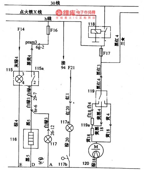
The central control door lock and rear window defroster connection circuit of Santana 2000
Published:2011/7/12 20:42:00 Author:Borg | Keyword: central control, door lock, Santana 2000
Figure: The central control door lock and rear window defroster connection circuit of Santana 2000 (gasoline injection engine)159-central interlock equipment; 160-right door interlock motor; 162-right door shutting micro switch; 115-rear window defroster switch lighting lamp; 115a-rear window defroster switch; 116-rear window defroster; 117-defroster indicator (View)
View full Circuit Diagram | Comments | Reading(875)
The general switch and off-loading relay connection circuit of Santana 2000(gasoline injection engine)
Published:2011/7/12 20:26:00 Author:Borg | Keyword: general switch, off-loading relay, gasoline injection engine
Figure: The general switch and off-loading relay connection circuit of Santana 2000(gasoline injection engine)36-light switch lamp; 101-light general switch; 102-instrument lamp regulating resistor; 118-off-loading relay (igniting switch X cylinder control) (View)
View full Circuit Diagram | Comments | Reading(504)
The connection circuit of Santana 2000 (gasoline injection engine)
Published:2011/7/12 21:17:00 Author:Borg | Keyword: connection circuit, Santana 2000
Figure: the fuel alarm lamp, air-conditioning fan and fuel pump connection circuit of Santana 2000 (gasoline injection engine)62-gas pressure alarm lamp switch; 61-gas pressure alarm lamp; 140-cooling fanⅡ; 141-cooling heat switch; 142-cooling fan; 134-fan delay switch; 135-cooling fan relay; 45-temperature sensor; 5-gasoline box pump; 5a-cold starting temperature switch. (View)
View full Circuit Diagram | Comments | Reading(344)
The connector circuit of Santana 2000 whole wires
Published:2011/7/12 21:40:00 Author:Borg | Keyword: connector circuit, Santana 2000
1-igniting pulse signal input 2-shield wire ground connection; 3- normally open contactor of throttle position sensor; 4-igniting switch 50 cylinder connection; 5-ground; 6-shorts; 7-air volume meter signal voltage; 8-admission temperature sensing signal; 9-fuel pump working signal voltage input terminal; 12-Ⅰand Ⅳ cylinder injector electromagnetic coil input terminal; 13-ground; 14-shorts; 15-17-pin of the EZK electric control unit; 16,17 and 18-shorts; 19-shield wire; 20-16-pin not in connection with EZK control unit; 21- 15 cylinder wire of the igniting switch (View)
View full Circuit Diagram | Comments | Reading(424)
The electric control rear-view mirror circuit of Santana 2000
Published:2011/7/13 20:37:00 Author:Borg | Keyword: electric control, rear-view mirror
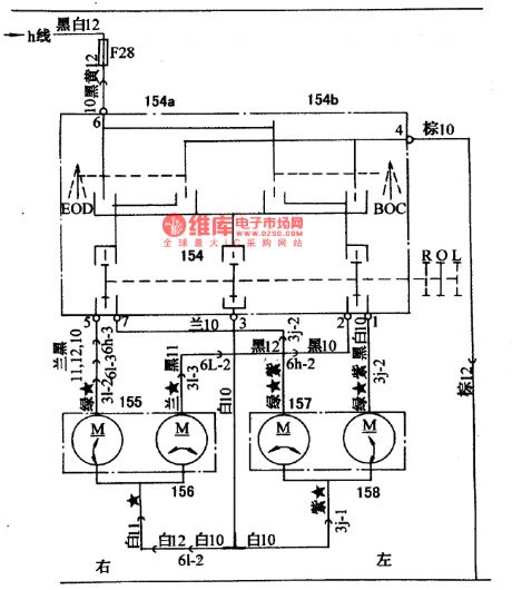
Figure: The electric control rear-view mirror circuit of Santana 2000 (gasoline injection engine)154-left/right rear-view mirror selecting switch; 154a-transverse regulation(left/right) twist switch; 154b-longitudinal regulation(upper/lower) twist switch; 155-the regulating motor of right rear-view mirror (upper/lower); 156-the regulating motor of right rear-view mirror (left/right); 157-the regulating motor of left rear-view mirror (upper/lower); 158-the regulating motor of left rear-view mirror (left/right); There is a rear-view mirror on either side of the front doors, which is convenient for the driver to see the cars, people and road behind the car. (View)
View full Circuit Diagram | Comments | Reading(1170)
The air-conditioning system circuit of Santana 2000(see as figure 1/2)
Published:2011/7/13 20:25:00 Author:Borg | Keyword: air-conditioning system, Santana 2000
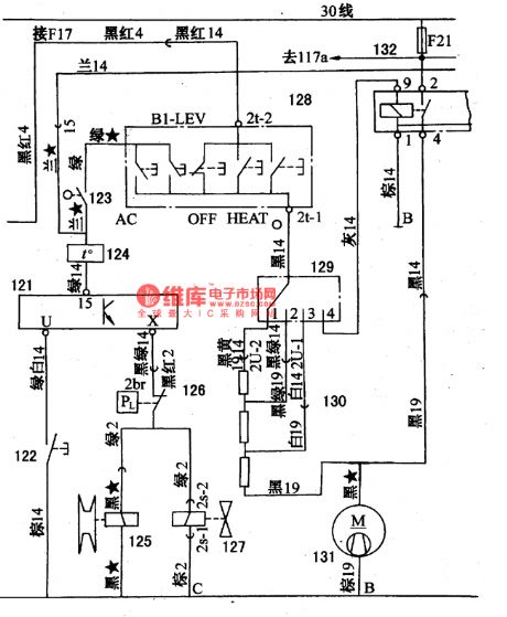
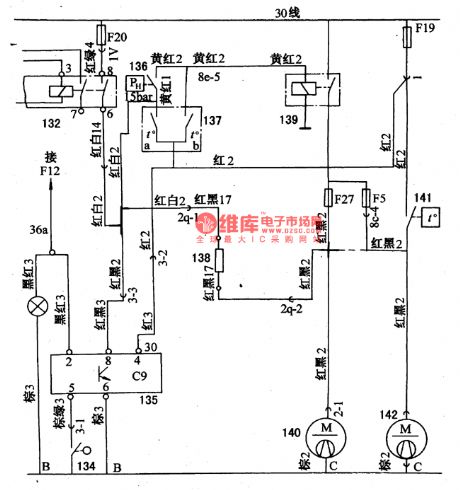
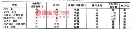
Figure 1 The air-conditioning system circuit of Santana 2000 (gasoline injection engine)36a-light switch lighting lamp; 121-over-load relay; 122-over-load relay switch; 123-micro switch; 124-thermostat; 125-air-conditioning compressor electromagnet clutch; 126-low-voltage switch(2bar); 127-the electromagnet valve of idle speed adjuster; 128-air-conditioning (H,V and A) control switch; 129-warm air speed switch(4 gears); 130-ventilation system air-conditioning resistor; 131-air-conditioning warm air blower; 132-air-conditioning relay
In the figure, there are 5 key switches on the air-conditioning system.
(View)
View full Circuit Diagram | Comments | Reading(526)
The wiper and washer of Santana 2000 (see as figure 1,2)
Published:2011/7/13 20:49:00 Author:Borg | Keyword: wiper, washer, Santana 2000
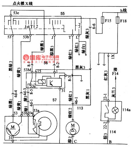
Under the contactor of off-load relay, there are fuses of F15, F16, FI7 and F18, and the relay 118 is under control of the igniting switch cylinder(which is cut off when the circuit is working normally), when the wiper switch 55 at the gear 1 , the current from the relay 118 is led to the 1st brush of the wiper motor 57 by the fuse F15, and it is sent to the armature rotor and the 2nd brush ground by black-green wires of 3 and 1. When the wiper switch is at the gear 2 , the current is coming out from 53b , then it is sent to the 2nd and 3rd brush grounds through green-yellow wires of 1 and 3.
(View)
View full Circuit Diagram | Comments | Reading(451)
The brake lamp and loudspeaker circuit of Santana 2000
Published:2011/7/13 21:32:00 Author:Borg | Keyword: brake lamp, loudspeaker circuit
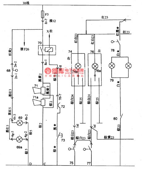
Figure: The brake lamp and loudspeaker circuit of Santana 2000 (gasoline injection engine)68-brake linked switch; 69-brake signal lamp(left); 69a-brake signal lamp(right); 70-loudspeaker relay; 71,a-loudspeaker; 72-contactor of direction grid and grouped switch; 73-loudspeaker key; 74-reading lamp; 74a-reading lamp switch; 75-door control switch (right); 76-reading lamp; 76a-reading lamp switch; 77-control switch(left); 78-sun glasses shield lighting lamp switch; 79-sun glasses shield lighting lamp (View)
View full Circuit Diagram | Comments | Reading(468)
The turning and danger signal connection circuit of Santana 2000 (gasoline injection engine)
Published:2011/7/12 20:35:00 Author:Borg | Keyword: danger signal, Santana 2000
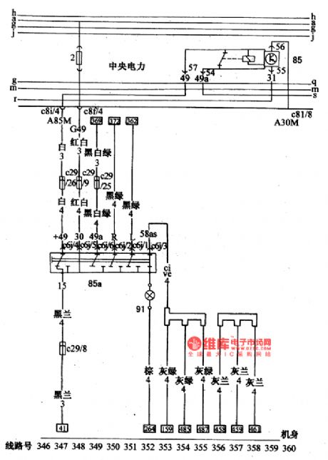
Figure: The turning and danger signal connection circuit of Santana 2000(gasoline injection engine)85-turning and danger signal flash relay; 85a-warning signal lamp switch; 91-the internal lighting lamp of warning lamp switch (View)
View full Circuit Diagram | Comments | Reading(413)
CX2O106A--the infrared tracking and control reception integrated circuit
Published:2011/7/12 3:14:00 Author:Borg | Keyword: infrared, integrated circuit
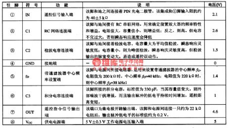
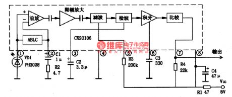
CX2O106A is an infrared tracking and control reception integrated circuit produced by Sony, Japan, which is widely used in the video, audio, air-conditioning, fan and so on as the remote signal reception circuit.1.pin functions and dataCX2O106A contains the remote signal reception, bandpass filtering, aftermath and other circuits. This IC is in 8-pin package, whose pin functions and data are listed in table 1.
Table 1.pin functions and data of CX20106A2.the internal circuit and typical application circuit
(View)
View full Circuit Diagram | Comments | Reading(685)
| Pages:150/195 At 20141142143144145146147148149150151152153154155156157158159160Under 20 |
Circuit Categories
power supply circuit
Amplifier Circuit
Basic Circuit
LED and Light Circuit
Sensor Circuit
Signal Processing
Electrical Equipment Circuit
Control Circuit
Remote Control Circuit
A/D-D/A Converter Circuit
Audio Circuit
Measuring and Test Circuit
Communication Circuit
Computer-Related Circuit
555 Circuit
Automotive Circuit
Repairing Circuit