
Signal Processing
Index 140
Simple sine wave generator composed of μA741
Published:2011/7/29 2:12:00 Author:Ecco | Keyword: Simple, sine wave , generator


The chart shows a simple sine wave generator circuit. The circuit can produce the sine wave with less distortion, the oscillation frequency:
According to the data presented in this chart, the oscillation frequency is about 25Hz. Changing the value of inductor L and capacitor C can change the oscillation frequency from 15Hz to 100kHz, the total harmonic distortion can be less than 0.5%, while the upper frequency limit is controlled by the operational amplifier. The potentiometer R1 can adjust the amount of positive feedback added to series resonant circuit. Oscillation condition is that resistor R1 should be equal to the inductance sum of DC resistor RL and inductor. Diode D1 is used to limit the signal voltage to prevent saturation of inductor and operational amplifier. In order to get the distortion as small as possible, the value of resistor R1 should be as low as possible, it but must be able to ensure the maintenance of oscillation.
(View)
View full Circuit Diagram | Comments | Reading(3117)
MODIFIED_HARTLEY_OSCILLATOR
Published:2009/6/23 2:18:00 Author:May

This oscillator uses a tapped coil in the collector circuit, with the tap grounded for the signal. L1 and L2 are coupled inductively and typically have a 3:1 turn ratio, and generally are sections of one entire winding. (View)
View full Circuit Diagram | Comments | Reading(1014)
455_kHz_OSCILLATOR
Published:2009/6/23 2:17:00 Author:May

The 455-kHz oscillator circuit uses a field-effect transistor (FET)for Q1. The output signal is taken from the source circuit of Q1. T1 is a 455-kHz IF transformer. (View)
View full Circuit Diagram | Comments | Reading(2540)
BUTLER_OSCILLATOR_CIRCUIT
Published:2009/6/23 2:15:00 Author:May


This circuit uses an overtone crystal in a Butler oscillator. L1 is approximately 1300μH, and the crystal frequency should be from 20 to 50 MHz. (View)
View full Circuit Diagram | Comments | Reading(1684)
BEAT_FREQUENCY_OSCILLATOR_FOR_AM/SW_RADIOS
Published:2009/6/23 2:14:00 Author:May

This BFO can be added to inexpensive AM/SW receivers to enable reception of CW signals. Output couples to base of last IF stage. T1 is any 455-kHz IF transformer. The BFO switch should be a DPDT type (as needed), and the radio AGC circuit will probably have to be disabled for CW reception. (View)
View full Circuit Diagram | Comments | Reading(1416)
REMOTE_OSCILLATOR_HIGH_FREQUENCY_VFO
Published:2009/6/23 2:12:00 Author:May


A remote VFO is sometimes used to control a transmitter or receiver. The circuit shown uses an MPF102 FET and is conyolled by a dc voltageat J3. The table shows values for L1 for various bands from 30 to 10 meters. U1 senres as a buffer amplifier. (View)
View full Circuit Diagram | Comments | Reading(918)
REINARTZ_OSCILLATOR
Published:2009/6/23 2:09:00 Author:May

This oscillator uses mauctivity coupled emitter and collector windings to its main tank circuit.Take care so that L1 and L2 are not coupled to each other, otherwise this circuit is susceptible to parasitic at other frequencies.Typically ,L1 has 5 to 10 times the number of turns that L2 has.L1,L2,L3 are woundon same coil form. This oscillator is more suited to lower frequencies,≤10 MHz. (View)
View full Circuit Diagram | Comments | Reading(0)
PSEUDO_RANDOM_BIT_SEQUENCE_GENERATOR
Published:2009/6/23 2:09:00 Author:May

In this circuit, an additional exclusive-OR gate is connected after the modulo-2 feedback, with C1 and R2 applying the supply turn-on ramp into the feedback loop. This provides sufficient transient signal so that the PRBS generator can self-start a power-up. A shift-register length n of 10 is shown with feedback at stages 3 and 10, providing true and inverted maximal length sequence outputs.
This technique applies an input directly to the feedback loop. Therefore, it's considered more reliable than applying an RC configuratior) to the shift-register reset input to create a random turnon state. (View)
View full Circuit Diagram | Comments | Reading(0)
AM_OSCILLATOR_FOR_WIRELESS_MICROPHONES
Published:2009/6/23 2:05:00 Author:May

This circuit will generate an AM-modulated signal in the AM broadcast band that can be picked up on a receiver.About 2V of audio input will produce about 30% modulation of the oscillator signal.An old AM broadcast oscillator coil or other two-winding coil with about a 10:1 turn ratio and about 50 to 150 μH inductance can be used for T1. (View)
View full Circuit Diagram | Comments | Reading(0)
JFET_VARIABLE_FREQUENCY_OSCILLATOR
Published:2009/6/23 2:01:00 Author:May

This simple JFET-based variable-frequency oscillator can be used in receiver and transmitter circuits. (View)
View full Circuit Diagram | Comments | Reading(0)
FREQUENCY_MODULATED_OSCILLATOR
Published:2009/6/23 2:00:00 Author:May

This circuit can be used for FM wireless audio, microphone, and part-15 applications where a stable frequency modulated oscillator is needed. LT can be varied to cover 75 to 150 MHz, as needed. (View)
View full Circuit Diagram | Comments | Reading(79)
COLPITTS_OSCILLATOR
Published:2009/6/23 1:58:00 Author:May

Here: L1≈7μH/f, C1≈C2≈C3≈2400pF/f, where.f is in MHz. In this circuit, the oscillator is free-running. (View)
View full Circuit Diagram | Comments | Reading(0)
CRYSTAL_OSCILLATOR_Ⅲ_
Published:2009/6/23 1:58:00 Author:May


These circuits are for use with a crystal-controlled LO usmg the NE602 C1,C2,and C3 arefor crystals in the 5-MHz region and are approx⒈mately chosen from
C3 is for fine tuning the crystal frequency and will be 20 to 50 pF typically. (View)
View full Circuit Diagram | Comments | Reading(996)
FREQUENCY_DOUBLER_AND_CRYSTAL_OSCILLATOR
Published:2009/6/23 1:56:00 Author:May

This frequency doubler produces a sine wave at twice the frequency of XTALl. Notice that the output is taken only from OUT B (pin 5), while OUT A (pin 4) is left open. (View)
View full Circuit Diagram | Comments | Reading(1067)
DIGITALLY_CONTROLLED_SQUARE_WAVE_OSCILLATOR
Published:2009/6/23 1:54:00 Author:May


IC1 LM3909 LED flasher/oscillator IC2 CD4066 quad bilateral switch C1,C2 0.1-μF capacitorC3 0.033-μF capacitorC4 0.047-μF capacitor
C5,C6 0.1-μF capacitorR1 2.2-kΩ, 1/4-W 5% resistorR2 10-kΩ potentiometerR3 2.7-kΩ, 1/4-W 5% resistorR4 470-Ω, 1/4-W 5% resistor (View)
View full Circuit Diagram | Comments | Reading(1179)
CRYSTAL_OSCILLATOR_WITH_ADJUSTABLE_FREQUENCY
Published:2009/6/23 1:53:00 Author:May

In this crystal oscillator circuit, C3 adjusts the frequency of the oscillator for exact netting. The crystal is a fundamental type. C1= 100 pF and C2 = 1000 pF are typicd. (View)
View full Circuit Diagram | Comments | Reading(1026)
dc_SWITCHED_CRYSTAL_OSCILLATOR
Published:2009/6/23 1:53:00 Author:May

This circuit is useful where several different crystal frequencies must be switched using a dc source. The values shown are typical for 40- to 60-MHz third-overtone crystals. Limitation on number of crystals depends on PIN diode capacitance and layout factors, but up to 5 or 10 crystals is possible. (View)
View full Circuit Diagram | Comments | Reading(653)
CRYSTAL_OSCILLATOR_Ⅱ
Published:2009/6/23 1:51:00 Author:May

An NE602 can be used as a crystal oscillator. (View)
View full Circuit Diagram | Comments | Reading(1023)
HARMONIC_GENERATOR
Published:2009/6/23 1:51:00 Author:May
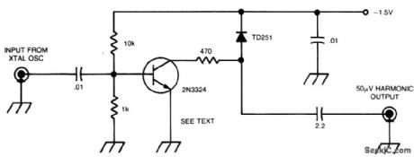
This circuit will produce 50 μV harmonics through 1296 MHz with an input of 0.15-1 V from a 100 or 1000 kHz crystal oscillator. With a germanium diode instead of a tunnel diode, harmonics can be heard up to about 147 MHz. (View)
View full Circuit Diagram | Comments | Reading(1)
Voltage-controlled duty cycle oscillator
Published:2011/7/28 2:13:00 Author:Ecco | Keyword: Voltage-controlled , duty cycle oscillator
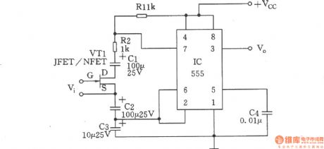
The circuit shown as the chart is a self-excited multivibrator composed of 555 timer. FET VTl is used as voltage-controlled resistor(VVR). By changing the source voltage VGS between a gate, you can change the resistance between JEFT drain (D) and source (S). Two coupling capacitors Cl and C2 can avoid the rest of the DC voltage from affecting on VTl. The value of the coupling capacitors Cl and C2should be10 times of timing capacitor, that will keep the coupling capacitor charging and discharging time from the influence of 555 timer. And at the same time, it will get a voltage variable resistor RDS between the D and S poles of VT1, and produce an empty cycle changing with VGS. RDS can reach 100kΩ. In order to obtain the maximum duty cycle variation, R2's value should take less. (View)
View full Circuit Diagram | Comments | Reading(1190)
| Pages:140/195 At 20121122123124125126127128129130131132133134135136137138139140Under 20 |
Circuit Categories
power supply circuit
Amplifier Circuit
Basic Circuit
LED and Light Circuit
Sensor Circuit
Signal Processing
Electrical Equipment Circuit
Control Circuit
Remote Control Circuit
A/D-D/A Converter Circuit
Audio Circuit
Measuring and Test Circuit
Communication Circuit
Computer-Related Circuit
555 Circuit
Automotive Circuit
Repairing Circuit