Oscillator Circuit
Voltage-controlled duty cycle oscillator
Published:2011/7/28 2:13:00 Author:Ecco | Keyword: Voltage-controlled , duty cycle oscillator | From:SeekIC
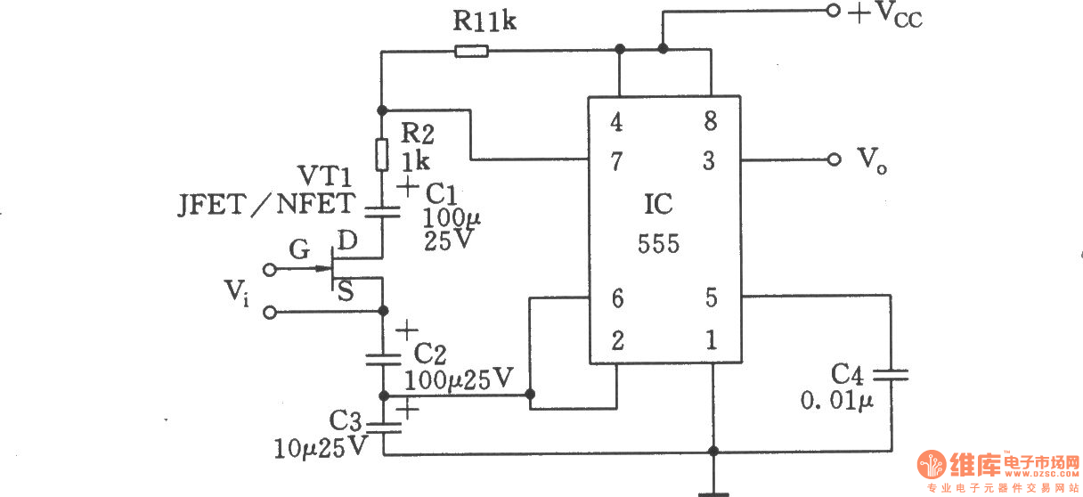
The circuit shown as the chart is a self-excited multivibrator composed of 555 timer. FET VTl is used as voltage-controlled resistor(VVR). By changing the source voltage VGS between a gate, you can change the resistance between JEFT drain (D) and source (S). Two coupling capacitors Cl and C2 can avoid the rest of the DC voltage from affecting on VTl. The value of the coupling capacitors Cl and C2should be10 times of timing capacitor, that will keep the coupling capacitor charging and discharging time from the influence of 555 timer. And at the same time, it will get a voltage variable resistor RDS between the D and S poles of VT1, and produce an empty cycle changing with VGS. RDS can reach 100kΩ. In order to obtain the maximum duty cycle variation, R2's value should take less.
Reprinted Url Of This Article:
http://www.seekic.com/circuit_diagram/Signal_Processing/Oscillator_Circuit/Voltage_controlled_duty_cycle_oscillator.html
Print this Page | Comments | Reading(3)

Article Categories
power supply circuit
Amplifier Circuit
Basic Circuit
LED and Light Circuit
Sensor Circuit
Signal Processing
Electrical Equipment Circuit
Control Circuit
Remote Control Circuit
A/D-D/A Converter Circuit
Audio Circuit
Measuring and Test Circuit
Communication Circuit
Computer-Related Circuit
555 Circuit
Automotive Circuit
Repairing Circuit
Code: