
Signal Processing
Index 130
Bell Signal Generator Circuit
Published:2011/7/21 0:49:00 Author:Joyce | Keyword: Bell, Signal , Generator

Bell signal generator is usually a calling signal source for communication equipment. Under the control of the automatic exchange system, oscillator for sending the call will produce frequency shift calling signals for the user to choose the one needs calling. The bell signal generator is composed of frequency shift control circuit, LC frequency shift oscillator and output circuit as shown in the figure.
(View)
View full Circuit Diagram | Comments | Reading(524)
Low Frequency Multi Wave Form Generator Circuit
Published:2011/7/22 21:13:00 Author:Joyce | Keyword: Low Frequency, Multi Wave Form, Generator

As shown in the figure is a low frequency multi waveform generator circuit. This circuit can output two kinds of waveform simultaneously: triangle wave and square wave. In the circuit, the first stage is a standard integrator; the second stage is a phase inverter whose gain is 1; the third stage is a hysteretic comparator. When the third stage does not have a diode, output of the circuit is positive, output of the integrator is negative inclined wave, which will turn into positive inclined wave after being inverted and will then be added to the comparator. (View)
View full Circuit Diagram | Comments | Reading(2173)
Wien Oscillation Audio Signal Generator Circuit
Published:2011/7/21 21:35:00 Author:Joyce | Keyword: Wien , Oscillation, Audio , Signal, Generator

Output frequency: 20 HZ -20 KHZ. Output amplitude: 2 V.It is simple, but has excellent performance and will meet the requirement of DIY acoustic equipment. Principle of the circuit: Operational amplifier CA3140 works as the major amplifier, 100 K potentiometer and phase shifting capacitance compose phase shift, positive feedback and frequency-selective network. 1 K potentiometer and thermistor constitute a negative feedback amplitude-stabilized circuit. Audio signal is output via the follower. (View)
View full Circuit Diagram | Comments | Reading(612)
74 Series digital circuit of 74LS324 VCO (dual-phase output with controlling)
Published:2011/8/1 20:11:00 Author:Lucas | Keyword: 74 Series, digital circuit , VCO, dual-phase output , controlling)

Output frequency is determined by the external components; it can works in the frequency of 30 ~ 120Hz; if the input is added 2V voltage in the frequency controlling range, the output frequency is approximately 0.0001CEXT , and there is complementary out.
(View)
View full Circuit Diagram | Comments | Reading(1013)
74 Series digital circuit of 74LS3237 dual voltage-controlled oscillator(single-phase output)
Published:2011/8/1 1:25:00 Author:Lucas | Keyword: 74 Series , digital circuit , dual voltage-controlled oscillator, single-phase output

Two independent voltage-controlled oscillators; external components can determine the output frequency; it works in any frequency between 0.12 and 30MHz.
(View)
View full Circuit Diagram | Comments | Reading(618)
The single knot transistor pulse transformer trigger thyristor circuit
Published:2011/7/21 3:15:00 Author:Seven | Keyword: single knot transistor, pulse transformer

View full Circuit Diagram | Comments | Reading(1195)
The thyristor stageless light and speed regulator circuit
Published:2011/7/21 3:18:00 Author:Seven | Keyword: thyristor, stageless, speed regulator

View full Circuit Diagram | Comments | Reading(432)
The dual-thyristor controlled 3-phase heating part circuit
Published:2011/7/21 3:20:00 Author:Seven | Keyword: dual-thyristor, 3-phase

View full Circuit Diagram | Comments | Reading(660)
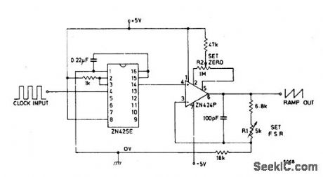
RAMP_GENERATOR_WITH_VARIABLE_RESET_LEVEL
Published:2009/6/26 3:05:00 Author:May

View full Circuit Diagram | Comments | Reading(0)
PRECISION_RAMP_GENERATOR
Published:2009/6/26 3:05:00 Author:May
View full Circuit Diagram | Comments | Reading(578)
CMOS_LINE_RECEIVER
Published:2009/6/26 3:45:00 Author:Jessie
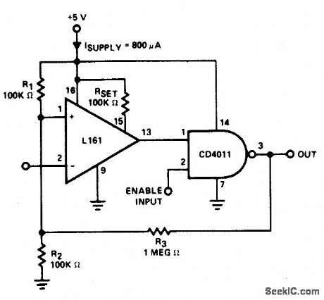
The trip point is set half way between the supplies by R1 and R2; R3 provides over 200 mV of hysteresis to increase noise immunity.Maximum frequency of operation is about 300 kHz. If response to TTL levels is desired, change R2 to 39 K. The trip point is now cen-tered at 1.4 V. (View)
View full Circuit Diagram | Comments | Reading(1610)
SIMPLE_LF_CONVERTER
Published:2009/6/26 3:44:00 Author:Jessie

This converter allows coverage from 25 kHz up to 500 kHz. Use short coax from the converter to receiver antenna input. Tune the receiver to 3.5 MHz, peak for loudest crystal calibrator and tune your receiver higher in frequency to 3.6 MHz and you're tuning the 100 kHz range. 3.7 MHz puts you at 200 kHz, 3.8 MHz equals 300 kHz, 3.9 MHz yields 500 kHz, and 4.0 MHz gives you 500 kHz. (View)
View full Circuit Diagram | Comments | Reading(1349)
FM_RADIO
Published:2009/6/26 3:43:00 Author:Jessie
View full Circuit Diagram | Comments | Reading(1209)
ANALOG_RECEIVER_LOW_TEMPERATURE_DRIFT
Published:2009/6/26 3:41:00 Author:Jessie

View full Circuit Diagram | Comments | Reading(982)
TRANSMITTER_OSCILLOSCOPE_COUPLER_FOR_CB_SIGNALS
Published:2009/6/26 2:24:00 Author:May

To display an rf signal, connect L1 to the transmitter and points A and B to the vertical plates of the oscilloscope. Adjust L1 for minimum SWR and C3 for the desired trace height on the CRT. L2 = 4 turns #18 on 3/4 slug tuned rf coil form, L1 = 3 turns #22 adjacent to grounded end of L1, C1, and C2 = 5 pF, C3 = 75 pF trimmer. (View)
View full Circuit Diagram | Comments | Reading(580)
107_MHz_SWEEP_GENERATOR
Published:2009/6/26 2:22:00 Author:May

This circuit is used to observe the response of an if amp or a filter. It can be used with an oscilloscope or,for more dynamic range,with a spectrum analyzer. (View)
View full Circuit Diagram | Comments | Reading(1488)
OSCILLOSCOPE_CONVERTER_PROVIDES_FOUR_CHANNEL_DISPLAYS
Published:2009/6/26 2:17:00 Author:May

The monolithic quad operational amplifier provides an inexpensive way to increase display capability of a standard oscilloscope. Binary inputs drive the IC op amp; a dual flip-flop divides the scope's gate output to obtain channel selection signals. All channels have cen-tering controls for nulling offset voltage. AL negative-going scope gate signal selects the next channel after each trace. The circuit operates out to 5 MHz. (View)
View full Circuit Diagram | Comments | Reading(798)
NOISE_GENERATOR_CIRCUIT
Published:2009/6/26 2:15:00 Author:May

The zener diode is an avalanche rectifier in the reverse bias mode connected to the input circuit of a wideband rf amplifier. The noise is amplified and applied to the cascade wideband amplifier, transistors Q2 and Q3. (View)
View full Circuit Diagram | Comments | Reading(1982)
WIDEBAND_NOISE_GENERATOR
Published:2009/6/26 2:14:00 Author:May

This circuit will produce wideband rf noise. It uses a reverse-biased diode and has a low-impedance output. Can be used to align receivers for optimum performance. (View)
View full Circuit Diagram | Comments | Reading(3034)
NOISE_GENERATOR
Published:2009/6/26 2:13:00 Author:May

The zener breakdown of a transistor junction is used as a noise generator. The breakdown mechanism is random and this voltage has a high source impedance. By using the op amp as a high input impedance, high ac gain amplifier, a low impedance, large signal noise source is obtained. The 100K potentiometer is used to set the noise level by varying the gain from 40 to 20 dB. (View)
View full Circuit Diagram | Comments | Reading(0)
| Pages:130/195 At 20121122123124125126127128129130131132133134135136137138139140Under 20 |
Circuit Categories
power supply circuit
Amplifier Circuit
Basic Circuit
LED and Light Circuit
Sensor Circuit
Signal Processing
Electrical Equipment Circuit
Control Circuit
Remote Control Circuit
A/D-D/A Converter Circuit
Audio Circuit
Measuring and Test Circuit
Communication Circuit
Computer-Related Circuit
555 Circuit
Automotive Circuit
Repairing Circuit