
Signal Processing
Index 137
WIEN_BRIDGE_OSCILLATOR_3
Published:2009/6/24 2:55:00 Author:May

View full Circuit Diagram | Comments | Reading(1644)
FREE_RUNNING_STAIRCASE_WAVE_GENERATOR
Published:2009/6/24 2:55:00 Author:May
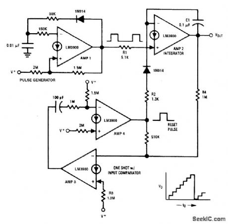
This free-running staircase generator uses all four of the amplifiers, which are available in one LM3900 package. Amp 1 provides the input pulses that pump up the staircase via resistor R1. Amp 2 does the integrate and hold function and also supplies the output staircase waveform. Amps 3 and 4 provide both a compare and a one-shot multivibrator function. Resistor R4 is used to sample the staircase output voltage and to compare it with the power supply voltage (V+) via R3. When the out-put exceeds approximately 80% of V+ the connection of Amps 3 and 4 causes a 100-ps reset pulse to be generated. This is coupled to the integrator (AMP2) via R2 and causes the staircase output voltage to fall to approximately 0 V. The next pulse out of Amp 1 then starts a new stepping cycle. (View)
View full Circuit Diagram | Comments | Reading(1664)
WIDE_RANGE_OSCILLATOR_FREQUENCY_RANGE_OF_5000_TO_1
Published:2009/6/24 2:54:00 Author:May

Timing resistor R may be adjusted to any value between 10 K and 50 M to obtain a fre-quency range from 400 kHz to 100 Hz. Return-ing the timing resistor to the collector of Q1 ensures that Q1 draws its base current only from the timing capacitor Ct. The timing capacitor recharges when the transistors are off, to a voltage equal to the base emitter volt-age of Q2 plus the base emitter drops ofQ1 and Q2. The transistors then start into conduction. Capacitor Cs is used to speed up the transition. A suitable value would be in the region of 100 pF. (View)
View full Circuit Diagram | Comments | Reading(899)
VIDEO_STAIRCASE_GENERATOR
Published:2009/6/24 2:54:00 Author:May
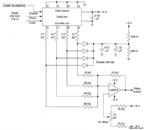
Using a 74HC161 counter and a simple D-A converter using an op amp and resistor network, a very simple video staircase generator for gray-scale generation (12 bars) can be obtained. The out-put is clean and mostly free of glitches. (View)
View full Circuit Diagram | Comments | Reading(1412)
TUNABLE_SINGLE_COMPARATOR_OSCILLATOR
Published:2009/6/24 2:53:00 Author:May
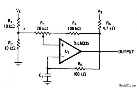
Varying the amount of this comparator circuit's hysteresis makes it possible to vary output frequencies in the 740-Hz to 2.7-kHz range smoothly. The amount of hysteresis to-gether with time constant R6C1 determines how much time it takes for C1 to charge or discharge to the new threshold after the output voltage switches. (View)
View full Circuit Diagram | Comments | Reading(1005)
STEPPED_TRIANGLE_WAVEFORM_GENERATOR
Published:2009/6/24 2:53:00 Author:May
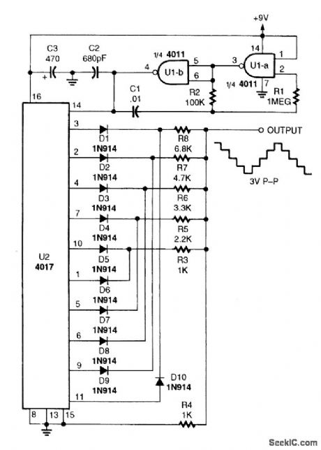
Two gates of a 4011 quad two-input NAND gate (U1) are connected in a pulse generator circuit.The square output at pin 4 of U1-b, connects to the clock input, pin 14, of a 4017 decade counter IC (U2). For each input clock pulse, the 4017 takes a single step. Because the 4017 counter is set up to count ten and then repeat the count, the stepped output frequency will only be Ho of the clock fre-quency. For a 100-Hz output, the clock generator must operate at 1 kHz.The 4017's positive output pulses begin at pin 3 and progress to pin 11 in a serial manner. The first output pulse, at pin 3, passes through Dl and R8 and appears across R4 to produce the first step up the triangle. The second pulse is routed through D2 and R7 to produce the second step. The out-puts at pins 10 and I form the top of the waveform and outputs at pins 5, 6, 9, and 11 produce the down steps. (View)
View full Circuit Diagram | Comments | Reading(4)
SQUARE_WAVE_GENERATOR
Published:2009/6/24 2:50:00 Author:May

A 60-Hz waveform from T1 drives an audio amplifier to clipping. Output is 60 Hz with about 0- to 1.4-V p-p amplitude. (View)
View full Circuit Diagram | Comments | Reading(2)
800_Hz_OSCILLATOR
Published:2009/6/24 2:46:00 Author:May

The following transistors may be used: HEP-254, O.C-2, SK-3004, AT30H. To increase the frequency, decrease the value of the capacitors in the ladder network. (View)
View full Circuit Diagram | Comments | Reading(0)
PHASE_SHIFT_OSCILLATOR
Published:2009/6/24 2:45:00 Author:May

A single transistor makes a simple phase shift oscillator. The output is a sine wave with distortion of about 104. The sine wave purity can be increased by putting a variable resistor (25 ohms) in the emitter lead of Q1 (x). The resistor is adjusted so the circuit is only just oscillating, then the sine wave is relatively pure. Operating frequency may be varied by putting a 10 K variable resistor In serles with R3,Or by changing C1,C2,and C3.Making C1,2, 3 equal to 100 nF will halve the operatingfrequency,Operating frequencycanalso bevoltage controlled by a FET In serles with R3,Or optically controlled by an LDR In serles with R3. (View)
View full Circuit Diagram | Comments | Reading(0)
ROBOTIC_CHATTER_SOUND_GENERATOR
Published:2009/6/24 2:44:00 Author:May


This circuit simulates sound effects of a robot, for toy or novelty applications.
(View)
View full Circuit Diagram | Comments | Reading(1578)
BIRD_CHIRP_SOUND_EFFECT_GENERATOR
Published:2009/6/24 2:42:00 Author:May
A low-frequency oscillator modulates a higher frequency oscillator, which drives the speaker. (View)
View full Circuit Diagram | Comments | Reading(982)
SURF_MAN_SOUND_GENERATOR
Published:2009/6/24 2:41:00 Author:May

Three low-frequency oscillators (IC1d, e, f) are used to simulate wave action of the surf. Q1 is an emitter-base junction used as a diode noise generator, biased by dc derived from oscillator ICl-c.The noise is fed into two voltage-controlled filters R22, R23, C12, C13, with D3 and D4 as tuning elements. The low-frequency oscillator signals randomly vary the filters, therefore, the spectrum of the noise signal fed through them. This simulates the sound of a surf. (View)
View full Circuit Diagram | Comments | Reading(768)
RECEIVER_AF_NOISE_LIMITER_FOR_LOW_LEVEL_SIGNALS
Published:2009/6/24 2:46:00 Author:Jessie

A preamplifier in the audio frequency range amplifies a noisy audio signal to drive a diode clip-per. Suitable audio input levels would be in the 10-mV to 1-V range. (View)
View full Circuit Diagram | Comments | Reading(1213)
FEEDBACK_OSCILIATOR
Published:2009/6/24 2:40:00 Author:May

Circuit oscillates because the transistor shifts the phase of the signal 180° from the base to the collector. Each of the RC networks in the circuit is designed to shift the phase 60°at the frequency of oscillation for a total of 180°. The appropriate values of R and C for each network is found from f = 1/2√3πRC); that equation allows for the 60°phase shift required by the design. (View)
View full Circuit Diagram | Comments | Reading(699)
DUAL_TONE_GENERATOR
Published:2009/6/24 2:39:00 Author:May
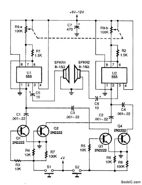
Two 555 oscillator/timers are configured similarly as audio oscillators, with each oscillator feeding a separate speaker.A dual 100-kQ potentiometer is use to tune the two oscillators simultaneously. The oscillators' frequency range is controlled by a dual-transistor switch, which selects the timing capacitor for both oscillators. Although the circuit only shows two range-switching circuits, any number can be added by simply duplicating the two-transistor switching circuit. (View)
View full Circuit Diagram | Comments | Reading(720)
COMPLEX_SOUND_EFFECT_GENERATOR
Published:2009/6/24 2:38:00 Author:May
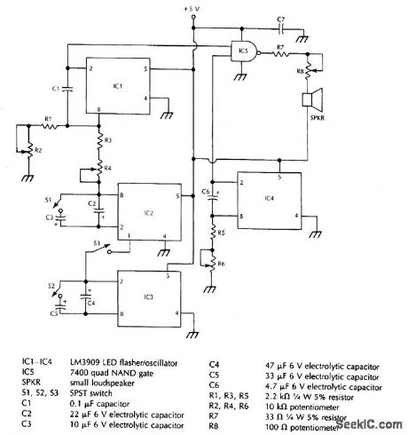
This system uses four free running oscillators to produce a wide variety of complex sounds. LF oscillator IC3 modulates IC2, which modulates IC1. The audio from IC1 is combined with a variable frequency from IC4. Switches at various points allow oscillators IC3 to be switched in or out, IC1 and IC2 to be varied in frequency, and IC4 also can be varied in frequency. The circuit is not critical and different arrangements can be tried to produce various sound effects. (View)
View full Circuit Diagram | Comments | Reading(1410)
PHASE_SHIFT_OSCILLATOR
Published:2009/6/24 2:33:00 Author:May

ircuit uses a simple RC network to pro-duce an exceptionally shrill tone from a minia-ture speaker. With the parts values shown, the circuit oscillates at a frequency of 3.6 kHz and drives a miniature 2 1/2 speaker with ear-piercing volume. The output waveform is a square wave with a width of 150 pts, sloping rise and fall times, and a peak-to-peak amplitude of 4.2 volts (when powered by 9 volts). Current drain of the oscillator is 90 mA at 9 volts, and total power dissipation at this voltage is 0.81 watt, which is well below the 1.25 watts the 14-pin version will absorb (at room temperature) before shutting down. (View)
View full Circuit Diagram | Comments | Reading(0)
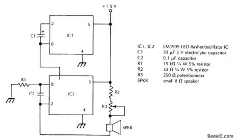
SIMPLE_CODE_PRACTICE_OSCILLATOR
Published:2009/6/24 2:33:00 Author:May

With only a minor circuit change, the basic LM3909 oscillator configuration can be turned into a code-practice oscillator. (View)
View full Circuit Diagram | Comments | Reading(0)
WIEN_BRIDGE_SINE_WAVE_OSCILLATOR
Published:2009/6/24 2:32:00 Author:May

Using the 2N5457 JFET as a voltage vari-able resistor in the amplifier feedback loop, produces a low distortion, constant amplitude sine wave getting the amplifier loop gain just right. The LM103 zener diode provides the voltage reference for the peak sine wave amplitude. (View)
View full Circuit Diagram | Comments | Reading(0)
EASILY_TUNED_SINE_SQUARE_WAVE_OSCILLATORS
Published:2009/6/24 2:31:00 Author:May

This circuit will provide both a sine and square wave output for frequencies from below 20 Hz to above 20 kHz. The frequency of oscillation is easily tuned by varying a single resistor. (View)
View full Circuit Diagram | Comments | Reading(0)
| Pages:137/195 At 20121122123124125126127128129130131132133134135136137138139140Under 20 |
Circuit Categories
power supply circuit
Amplifier Circuit
Basic Circuit
LED and Light Circuit
Sensor Circuit
Signal Processing
Electrical Equipment Circuit
Control Circuit
Remote Control Circuit
A/D-D/A Converter Circuit
Audio Circuit
Measuring and Test Circuit
Communication Circuit
Computer-Related Circuit
555 Circuit
Automotive Circuit
Repairing Circuit