
Signal Processing
Index 133
MILLER_OSCILLATOR_CRYSTAL_CONTROLLED
Published:2009/6/25 2:24:00 Author:May

Circuit Notes
The drain of the JFET Miller oscillator is tuned to the resonant frequency of the crystal by an LO tank circuit. (View)
View full Circuit Diagram | Comments | Reading(1331)
PRECISION_CLOCK_GENERATOR
Published:2009/6/25 2:23:00 Author:May
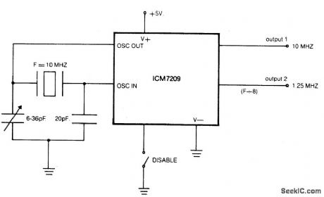
Circuit NotesThe CMOS IC directly drives 5 TTL loads from either of 2 buffered outputs. device operates to 10 MHz and is bipolar, MOS, and CMOS compatible. (View)
View full Circuit Diagram | Comments | Reading(680)
TUBE_TYPE_CRYSTAL_OSCILLATOR
Published:2009/6/25 2:20:00 Author:May

Circuit Notes
The pilot lamp limits current to prevent damage to the crystal. (View)
View full Circuit Diagram | Comments | Reading(754)
PIERCE_HARMONIC_OSCILLATOR(BASIC_CIRCUIT)
Published:2009/6/25 2:20:00 Author:May

Circuit Notes
This circuit operates 10-40 ppm above series resonance. It is a good circuit design with good to very good frequency stability. (View)
View full Circuit Diagram | Comments | Reading(789)
BUTLER_COMMON_BASE_OSCILLATOR_BASIC_CIRCUIT
Published:2009/6/25 2:17:00 Author:May

Circuit Notes This circuit operates at or near series resonance. It has fair to poor circuit design with parasitics, touch to tune, and fair frequency stability. (View)
View full Circuit Diagram | Comments | Reading(0)
COLPITTS_HARMONIC_OSCILLATOR(BASIC_CIRCUIT)
Published:2009/6/25 2:14:00 Author:May

Circuit NotesThis circuit operates 30-200 ppm above series resonance. Physically simple, but analytically complex. It is inexpensive with fair frequency stability. (View)
View full Circuit Diagram | Comments | Reading(0)
INTERNATIONAL_CRYSTAL_OF_1_LO_OSCILLATOR
Published:2009/6/25 2:04:00 Author:May
Circuit Notes
International Crystal OF-1 LO oscillator circuit for fundamental-mode crystals. (View)
View full Circuit Diagram | Comments | Reading(605)
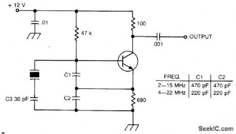
COLPITTS_HARMONIC_OSCILLATOR(100_MHz)
Published:2009/6/25 2:03:00 Author:May
Circuit Notes
L1C1 are selected to be resonant at a frequency below the desired crystal harmonic but above the crystal's next lower odd har-monic. C2 should have a value of 30-70 pF, independent of the oscillation frequency.There is no requirement for any specific ratio of C1/C2, but practical harmonic circuits seem to work best when C1 is approximately 1-3 times the value of C2. Diodes Dl-D3 provide a simple regulated bias supply. The resistance of RI should be as high as possible, as it affects the crystal's in-circuit Q. (View)
View full Circuit Diagram | Comments | Reading(821)
TEMPERATURE_COMPENSATED_CRYSTAL_OSCILLATOR
Published:2009/6/25 1:51:00 Author:May

Circuit NotesTwo different negative-coefficient capacitors change in capacitance to counteract or compensate are blended to produce the desired for the decrease in frequency of the normal AT-cut characteristics. (View)
View full Circuit Diagram | Comments | Reading(0)
CMOS_CRYSTAL_OSCILLATOR
Published:2009/6/25 1:47:00 Author:May


Circuit Notes
This circuit has a frequency range of 0.5 MHz to 2.0 MHz. Frequency can be adjusted to a precise value with trimmer capacitor C2. The second NOR gate serves as an output buffer. (View)
View full Circuit Diagram | Comments | Reading(1975)
THIRD_OVERTONE_CRYSTAL_OSCILLATOR
Published:2009/6/25 1:42:00 Author:May

Circuit NotesThis circuit uses a 74500 Schottky TTL gate; no inductors are required. (View)
View full Circuit Diagram | Comments | Reading(857)
HIGH_VOLTAGE_dc_GENERATOR
Published:2009/6/24 23:50:00 Author:May

In the miniature high-voltage dc generator, the input to the circuit, taken from a 12-Vdc power supply, is magnified to provide a 10,000-Vdc output causing a pulsating signal, of opposite polarity, to be induced in T1's secondary winding.
The pulsating dc output at the secondary winding of T1 (ranging from 800 to 1000 V) is applied to a 10-stage voltage-multiplier circuit, which consists of D1 through D10, and C3 through C12. The multiplier circuit increased the voltage 10 times, producing an output of up to 10,000 Vdc. The mul-tiplier accomplishes its task by charging the capacitors (C3 through C12); the output is a series ad-dition of the voltages on all the capacitors in the multiplier.
In order for the circuit to operate efficiently, the frequency of the square wave, and therefore the signal applied to the multiplier, must be considered. The output frequency of the oscillator (U1-a) is set by the combined values of R1, R5, and C1 (which with the values specified is approximately 15 kHz). Potentiometer R5 is used to fine tune the output frequency of the oscillator. The higher the frequency of the oscillator, the lower the capacitive reactance in the multiplier.
Light-emitting diode LED1 serves as an input-power indicator, and neon lamp NE1 indicates an output at the secondary of T1. A good way to get the maximum output at the multiplier is to connect an oscilloscope to the high-voltage output of the multiplier, via a high-voltage probe, and adjust potentiometer R5 for the maximum voltage output. (View)
View full Circuit Diagram | Comments | Reading(2432)
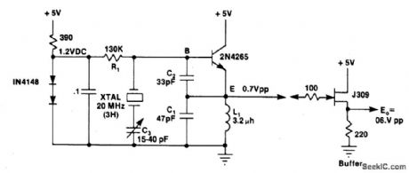
LOW_FREQUENCY_CRYSTAL_OSCILLATOR
Published:2009/6/24 23:31:00 Author:May
Circuit NotesThis crystal-oscillator circuit uses crystal. (View)
View full Circuit Diagram | Comments | Reading(0)
CRYSTAL_OSCILLATOR_DOUBLER
Published:2009/6/24 23:30:00 Author:May

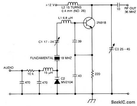
Circuit Notes
The crystal operates into a complex load at series resonance. L1, C1, and C2 balance the crystal at zero reactance. Capacitor C1 fine-tunes the center frequency. Tank circuit L2, C3 doubles the output frequency the circuit operates as an FM oscillator-doubler. (View)
View full Circuit Diagram | Comments | Reading(839)
OVERTONE_OSCILLATOR_WITH_CRYSTAL_SWITCHING
Published:2009/6/24 23:18:00 Author:May

Circuit Notes
The large inductive phase shift of L1 is compensated for by C1. Overtone crystals have very narrow bandwidth; therefore, the trimmer has a smaller effect than for fundamental-mode operation. (View)
View full Circuit Diagram | Comments | Reading(0)
CRYSTAL_CONTROLLED_BUTLER_OSCILLATOR
Published:2009/6/24 23:13:00 Author:May

Circuit NotcsA typical Butler oscillator (20-100 MHz) uses an FET in the second stage; the circuit is not reliable with two bipolars. Sometimes two FETs are used. Frequency is determined by LC values. (View)
View full Circuit Diagram | Comments | Reading(0)
FIFTH_OVERTONE_OSCILLATOR
Published:2009/6/24 23:06:00 Author:May

Circuit NotesThis circuit isolates the crystal from the dc base supply with an rf choke for better starting characteristics. (View)
View full Circuit Diagram | Comments | Reading(0)
50_MHz_150_MHz_OVERTONE_OSCILLATOR
Published:2009/6/24 23:02:00 Author:May

View full Circuit Diagram | Comments | Reading(0)
SCHMITT_TRIGGER_CSCILLATOR
Published:2009/6/24 22:57:00 Author:May
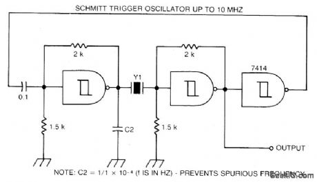
Circuit NotesA Schmitt trigger provides good squaring of the output, sometimes eliminating the need for an extra output stage. (View)
View full Circuit Diagram | Comments | Reading(774)
WHITE_NOISE_GENERATOR
Published:2009/6/24 22:33:00 Author:May

Here, a 2N3904 E-B junction is used as a noise generator, reversed bias. C is chosen to pass the lowest-desired frequency components of the noise. (View)
View full Circuit Diagram | Comments | Reading(2559)
| Pages:133/195 At 20121122123124125126127128129130131132133134135136137138139140Under 20 |
Circuit Categories
power supply circuit
Amplifier Circuit
Basic Circuit
LED and Light Circuit
Sensor Circuit
Signal Processing
Electrical Equipment Circuit
Control Circuit
Remote Control Circuit
A/D-D/A Converter Circuit
Audio Circuit
Measuring and Test Circuit
Communication Circuit
Computer-Related Circuit
555 Circuit
Automotive Circuit
Repairing Circuit