
Signal Processing
Index 122
100_kHz_SINE
Published:2009/7/2 1:06:00 Author:May

Tunnel-diode sine-wave oscillator uses single GE 2J-69. Frequency is stable provided there are no drastic temperature changes, but for long-term accuracy and stability a crystal oscillator is recommended.-Circuits, 73 Magazine, May 1977, p 31. (View)
View full Circuit Diagram | Comments | Reading(968)
279611_kHz_CRYSTAL
Published:2009/7/2 1:05:00 Author:May

DT-cut quartz crystal operating in CMOS inverter pair circuit serves as efficienttiming circuit. Supply voltage can be from 5 to 15 V. With TA5987 Low-voltage equivalent of 4007, supply can be 2.5 to 5 V. Stability is 4.3 PPM, not including temperature variations.-B. Furlow, CMOS Gates in Linear Applications: The Results Are Surprisingly Good, EDN Magazine, March 5, 1973, p 42-48. (View)
View full Circuit Diagram | Comments | Reading(685)
5_MHz_LOW_NOISE_CRYSTAL
Published:2009/7/2 1:03:00 Author:May

Extremely low-noise series-mode crystal oscillatoris designedfor use in high-quality communication receivers. Eitherfundamental or overtone crystals can be used.-U. L. Rohde, Effects of Noise in Receiving Systems, Ham Radio, Nov. 1977, p 34-41. (View)
View full Circuit Diagram | Comments | Reading(787)
VCO_SOUND_SYNTHESIZER
Published:2009/7/2 0:43:00 Author:May

Developed for use in instrument capable of duplicating variety of sounds ranging from bird distress calls and engine noises to spoken words and wide variety of musical instruments. Three-part article gives all circuits and describes their operation in detail. Heart of oscillator is triangle and square-wave generator built around IC Schmitt trigger. Ramp rate and operating frequency are varied by changing drive voltage or gain of integrator. Similar VCO in synthesizer also produces sine, pulse, and ramp waveforms.-T. Orr and D. W. Thomas, Electronic sound synthesize, Wire-less World, part 1-Aug. 1973, p 429-434; Part 3-Oct. 1973, p 485-490. (View)
View full Circuit Diagram | Comments | Reading(817)
GATE_DIP_FET_OSCILLATOR_
Published:2009/7/1 23:51:00 Author:May

Meter indicates gate current, which drops whenever resonant load is placed on tank circuit of oscillator by bringing plug-in input coil near frequency source being checked. By opening switch to power supply, circuit can be used as absorption wavemeter; when signal at resonant frequency of dip-meter tank circuit is picked up, gatesource circuit of FET operates as diode detector for producing increase in meter reading. Values of plug-in coil and tuning capacitor depend on frequency range of interest.-E. M. Noll, FET Principles, Experiments, and Projects, Howard W. Sams, Indianapolis, IN, 2nd Ed., 1975, p 213-214. (View)
View full Circuit Diagram | Comments | Reading(3446)
ORGAN_TONE_GENERATOR
Published:2009/7/1 23:50:00 Author:May
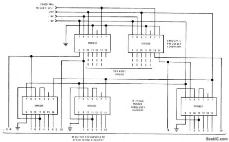
National MM5824 and MM5824 chromatic frequency generators are used with 12 MM5824 frequency dividers to generate 85 musical frequencies fully spanning equal-tempered octave. Can also be used as celeste or chorus tone generator and as electronic music synthesizer. Square-wave inputfor organ is 2.00024 MHz but can be as low as 7 kHz for other applications -''MOS/LSI Databook.'' national Semiconductor .Santa Clara. CA .1977.p3-11-3-13. (View)
View full Circuit Diagram | Comments | Reading(1905)
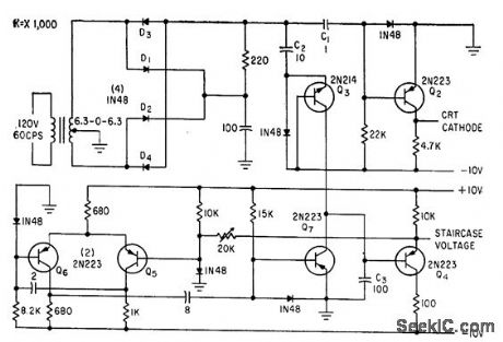
TWO_SECTION_STAIRCASE
Published:2009/7/24 3:07:00 Author:Jessie
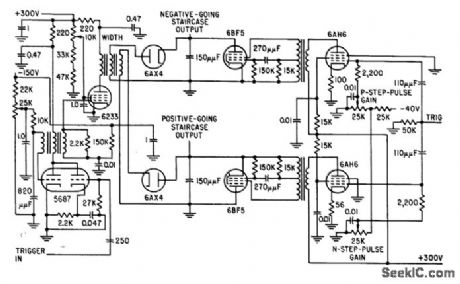
Negative-going staircase is developed from positive potential, and positive-going staircase from negative potential. Output voltage across 150-mmfd capacitors is 800V peak-to-peak, enough to drive crt directly.-M. T. Nadir, Microsecond Sampler Handles 126 Channels, Electronics, 32:4, p 36-39. (View)
View full Circuit Diagram | Comments | Reading(561)
64_STEPS
Published:2009/7/24 3:04:00 Author:Jessie
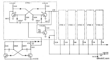
R-C dock, six binary counters, and summing network give repetitive staircase waveform having 64 equally spaced potential steps between and including minimum and maximum voltages. Free-running astable mvbr (lower left) generates 40-cps dock signal. Transistors can be 2N697.-E. E. Eberhard, Latest Thin-Film Circuit Techniques, Electronics, 35:24, p 37-39. (View)
View full Circuit Diagram | Comments | Reading(524)
STAIRCASE_GENERATOR
Published:2009/7/24 3:01:00 Author:Jessie
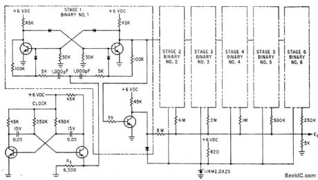
Major modification of conventional 64step voltage staircase generator for integrated-circuit construction involved dropping supply voltage from 15 V to 0 V, To cut power drain in half and reduce summing resistor network values. Circuit uses Pacific Semiconductor PD101 microdiodes and uncased Fairchild ESP-42-1 transistors.-E. E. Eberhard, Latest Thin-Film Circuit Techniques, Electronics, 35:24, p 37-39. (View)
View full Circuit Diagram | Comments | Reading(0)
SAMPLING_STAIRCASE
Published:2009/7/24 3:00:00 Author:Jessie
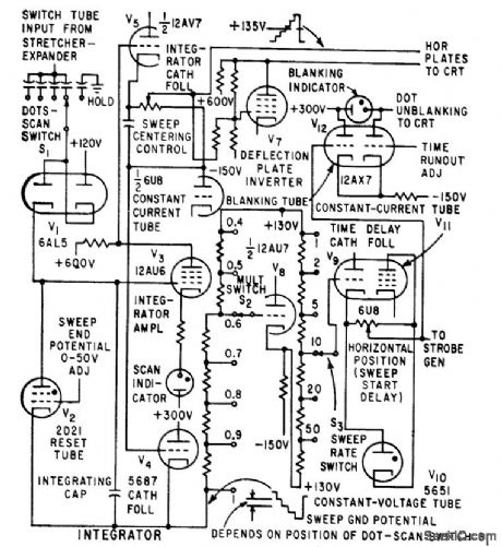
Provides horizontal def action voltage for crt and time advance information for comparator tube in strobe generator. Increase of d-c bias superimposed on staircase advances start of sampling with respect to start of ramp, decreasing op parent lime delay in start of d-c trace. Blanking indicator in staircase generator is on when screen is blanked. Scan indicator lashes when staircase is sweeping. Staircase advances one stop for each displayed sample.-W. E. Bushor, Sample Method Displays Millimicrosecond Pulses, Electronics, 32:31, p 69-71. (View)
View full Circuit Diagram | Comments | Reading(638)
GRID_DIP_OSCILLATOR
Published:2009/7/1 21:52:00 Author:May

Millen 90652 solidstate grid-dip oscillator uses MOSFET operating in split-Colpitts circuit with resonating tank connected between drain and gate. Circuit is tuned by split-stator variable capacitor with rotorgrounded, chosen to cover 1.7 to 300 MHz with seven plug-in coils. Oscillator also functions as Q multiplier that increases sensitivity.RF voltage across tuned circuit is indicated by meter whose reading dips for resonance with coupled test circuit. Full-wave rectifier CR1-CR2 provides DC voltage for meter and some overload protection for MOSFET. Meter is suppressed-zero type, with readings only for upper portion of current range. J3 is provided for use with low-frequency coils.-W. M. Scherer,CQ Reviews: The Millen Model 90652 Solid-State Dipper, CQ, Sept. 1971, p 63-64, 66, and 96. (View)
View full Circuit Diagram | Comments | Reading(4710)
WAVEFORM_GENERATOR_FOR_CURVE_TRACER
Published:2009/7/24 3:06:00 Author:Jessie
Generates blanking signal at collector of Q2 and staircase waveform at emitter of Q4 by charge transfer from C2 to C3.-C. J. Candy, Simplified Curve Tracer for Transistors and Diodes, Electronics, 33:34, p 68-70. (View)
View full Circuit Diagram | Comments | Reading(727)
PIANO_TONE_GENERATOR
Published:2009/7/1 21:41:00 Author:May
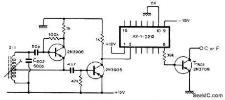
RF oscillator combined with General Instrument AY-1-0212 IC mastertonegenerator replaces 12 conventional RC oscillators otherwise required in electronic piano. Frequencies generated are within 0.1% of equal-temperament scale, so piano will work well without being tuned. Three-part article gives all circuits and construction details for simple portable touch-sensitive electronic piano.-G, Cowie, Electronic Piano Design, Wireless World, Part 3, May 1974, p 143-145. (View)
View full Circuit Diagram | Comments | Reading(1918)
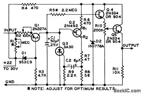
SINGLE_STEPS_AT_100_KC
Published:2009/7/24 3:05:00 Author:Jessie
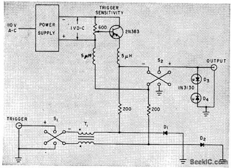
Tunnel-diode step generator provides single 400-my steps that are fast and free from overshoot, for testing wideband systems. Flat top of step, used for tests, is 2 microsec long. Step can be triggered with 0.5-V signal at repetition rates to 100 kc, or can free-run at about 100 kc.-R.Carlson, Tunnel-Diode Fast-Stop Generator Produces Positive or Negative Steps, Electronics, 34:30, p 48-49. (View)
View full Circuit Diagram | Comments | Reading(504)
LOW_FREQUENCY_STAIRSTEP
Published:2009/7/24 3:02:00 Author:Jessie
Accepts pulse input, either random or evenly spaced, and produces output ofter fixed number of inputs. Useful in measuring and recording low. frequency data. Pulse widths may be 1 millisec to several hundred millisec. Output may have anywhere from 2 to 1,000 steps.By making R1 smaller and eliminating R2, output becomes sawtooth with 1% linearity, variable from 10 millisec to 15 minutes depending on values of C1 and R1.-Low.Frequency Stairstep Generator and Timing Circuit, Electronic Circuit Design Handbook, Mactier Pub. Corp., N.Y., 1965, p 144. (View)
View full Circuit Diagram | Comments | Reading(578)
FET_DIP_OSCILLATOR
Published:2009/7/1 21:10:00 Author:May

High input impedance of FET makes performance comparable to that of tube-type grid-dip oscillator. Six plug-in coils are wound on Millen 45004 1-inch 4-pin forms or equivalent. Use 150 turns No. 32 enamelfor 1.1-2.5 MHz, 77 turns No. 28 for 2.5-5 MHz, 35 turns No. 22 for 5-11 MHz, 17 turns No. 22 spaced to 1 inch for 10-25 MHz, 8.5 turns No. 22 spaced to 1 inch for 20-45 MHz and 4.5 tums No. 22 spaced to 1 inch for 40-95 MHz. Adjust R1 to set meter pointer to desired portion of scale before tuning for dip. R1 provides some control of volume when using headphones.-R.P. Turner, FET Circuits, Howard W. Sams, Indianapolis, IN, 1977, 2nd Ed., p 134-136. (View)
View full Circuit Diagram | Comments | Reading(4716)
VOLTAGE_CONTROLLED_OSCILLATOR_2
Published:2009/7/1 21:04:00 Author:May

View full Circuit Diagram | Comments | Reading(671)
VOLTAGE_CONTROLLED_OSCILLATOR_1
Published:2009/7/1 21:03:00 Author:May

View full Circuit Diagram | Comments | Reading(689)
TWO_DECADE_HIGH_FREQUENCY_VCO
Published:2009/7/1 21:02:00 Author:May

View full Circuit Diagram | Comments | Reading(764)
LVDT_signal_conditioner_mechanical_position
Published:2009/7/24 3:23:00 Author:Jessie
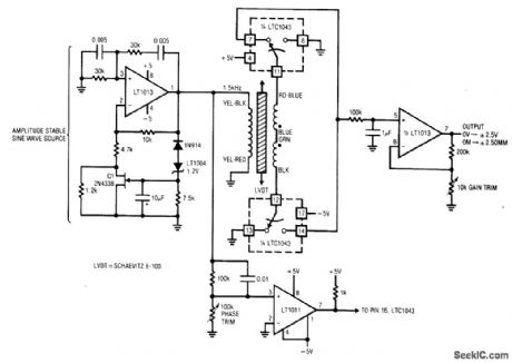
Fig. 14-2 This circuit converts mechanical position (±2.5 mm) into a corresponding output voltage (±2.5 V) using an LVDT (linear variable differential transformer) and an LTC1043 switched-capacitor IC. An LVDT is a transformer with a mechanically actuated core. The primary is driven by a stable sine wave. Two secondaries are connected in opposed phase. When the core is positioned in the magnetic center of the transformer, the secondary outputs cancel and there is no output. Moving the core away from the center position unbalances the flux ratio between the secondaries and develops an output. The output is positive when the core moves in one direction and negative when the core moves in the opposite direction. The circuit output thus indicates how far the core is from center and on which side. To calibrate, center the LVDT core in the transformer and adjust the phase trim for 0-V output. Next, move the core to either extreme position and set the gain trim for 2.50-V output (either positive or negative, depending on which direction the core is positioned). Linear Technology Linear Applications Handbook, 1990. p. AN3-9. (View)
View full Circuit Diagram | Comments | Reading(5130)
| Pages:122/195 At 20121122123124125126127128129130131132133134135136137138139140Under 20 |
Circuit Categories
power supply circuit
Amplifier Circuit
Basic Circuit
LED and Light Circuit
Sensor Circuit
Signal Processing
Electrical Equipment Circuit
Control Circuit
Remote Control Circuit
A/D-D/A Converter Circuit
Audio Circuit
Measuring and Test Circuit
Communication Circuit
Computer-Related Circuit
555 Circuit
Automotive Circuit
Repairing Circuit