Signal Processing
LVDT_signal_conditioner_mechanical_position
Published:2009/7/24 3:23:00 Author:Jessie | From:SeekIC

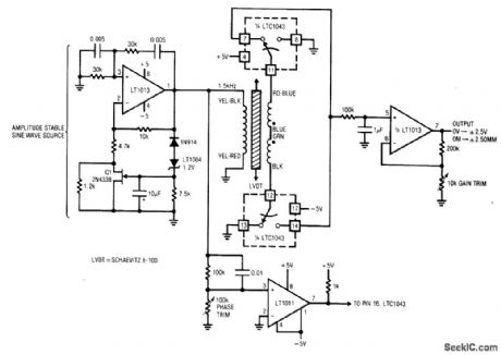
Fig. 14-2 This circuit converts mechanical position (±2.5 mm) into a corresponding output voltage (±2.5 V) using an LVDT (linear variable differential transformer) and an LTC1043 switched-capacitor IC. An LVDT is a transformer with a mechanically actuated core. The primary is driven by a stable sine wave. Two secondaries are connected in opposed phase. When the core is positioned in the magnetic center of the transformer, the secondary outputs cancel and there is no output. Moving the core away from the center position unbalances the flux ratio between the secondaries and develops an output. The output is positive when the core moves in one direction and negative when the core moves in the opposite direction. The circuit output thus indicates how far the core is from center and on which side. To calibrate, center the LVDT core in the transformer and adjust the phase trim for 0-V output. Next, move the core to either extreme position and set the gain trim for 2.50-V output (either positive or negative, depending on which direction the core is positioned). Linear Technology Linear Applications Handbook, 1990. p. AN3-9.
Reprinted Url Of This Article:
http://www.seekic.com/circuit_diagram/Signal_Processing/LVDT_signal_conditioner_mechanical_position.html
Print this Page | Comments | Reading(3)

Article Categories
power supply circuit
Amplifier Circuit
Basic Circuit
LED and Light Circuit
Sensor Circuit
Signal Processing
Electrical Equipment Circuit
Control Circuit
Remote Control Circuit
A/D-D/A Converter Circuit
Audio Circuit
Measuring and Test Circuit
Communication Circuit
Computer-Related Circuit
555 Circuit
Automotive Circuit
Repairing Circuit
Code: