
Signal Processing
Index 143
SIMPLE_SIGNAL_GENERATOR_FOR_SIGNAL_TRACING
Published:2009/6/22 17:50:00 Author:May

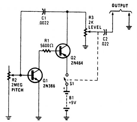
A simple R-C oscillator generates a harmonic-rich waveform for signal injection. (View)
View full Circuit Diagram | Comments | Reading(689)
2NEGATIVE_ION_GENERATOR
Published:2009/6/19 4:58:00 Author:May
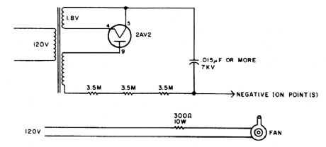
In this circuit, air is circulated past a pointed electrode that has a high negative voltage applied to it. The transformer is a small 4- to 6-kV output type with a filament winding. A good source of parts is a discarded electronic bug catcher. (View)
View full Circuit Diagram | Comments | Reading(802)
1NEGATIVE_ION_GENERATOR
Published:2009/6/19 4:56:00 Author:May

An NE555 drives a Darlington connected pair of transistors. T1 is a small high-voltage trans-former or auto ignition coil, B/W TV flyback, etc. C3, C4, and D1 must be rated for 10 to 15 kV. The fan blows air across the discharge point. (View)
View full Circuit Diagram | Comments | Reading(2495)
567 FM demodulator
Published:2011/7/17 23:02:00 Author:zj | Keyword: FM demodulator

As shown in Figure it is 567 FM demodulation circuit. In the figue, the FM signalenters from the 3 foot, the demodulated signal goes out from 5 foot. FM signal center frequency which the circuit can demodulateis: fo = 1.1 / RC, C1 isfilter capacitor, and C2 is bandwidth adjustment capacitor. WhenC2 decreases, the demodulator demodulating bandwidth increases. The circuitalso hasdemodulation circuit. When the demodulation is correct, 8 footoutput level is low. The indicating lamp, indicator light, also can be removed and used as control signals. (View)
View full Circuit Diagram | Comments | Reading(2050)
Digital frequency shift demodulator(CA3020、MC723、MC724)
Published:2011/7/18 20:22:00 Author:zj | Keyword: Digital, frequency shift, demodulator
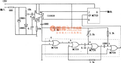
As shown in the figure it is the digital frequency demodulation circuit. The circuit can be used in 1kHz to 10kHz frequency range, and can be demodulated to the 1% frequency offset. The input stage of the circuit is composed of wide band amplifier CA3020. The differential output is added to the J-K input end of J-K trigger. Gate circuit MC724 constitutes the monostable multivibrator. Monostable multivibrator timing cycle is equal to the center frequency of the half cycle. Input signal strobes trigger after being delayed by the monostable multivibrator. (View)
View full Circuit Diagram | Comments | Reading(536)
WIDE_RANGE_FUNCTION_GENERATOR
Published:2009/6/19 3:24:00 Author:May
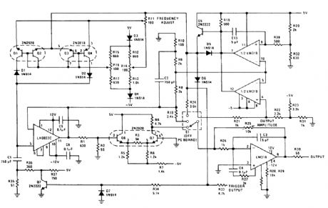
The sine, square, triangle function generator is exceptionally useful. Various IC circuits have been published for generating square and triangle waveforms in an attempt to duplicate the general-purpose function generator. However, these simple circuits are usually limited to about 10 kHz and have no sine-wave output. The function generator shown here provides all three waveforms and operates from below 10 Hz to 1 MHz with usable output to about 2 MHz. (View)
View full Circuit Diagram | Comments | Reading(2556)
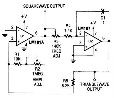
ACCURATE,STABLE_FUNCTION_GENERATOR
Published:2009/6/19 3:21:00 Author:May

Supply-limited oscillators usually are sensitive to temperature and power-supply changes, are never symmetrical, and don't operate at high frequencies because the amplifier's output is saturated when it reaches the supply lines.The circuit shown, a function generator, can alleviate these problems. Its square-wave output boasts a rapid rise time, quick settling time, and an amplitude that's temperature insensitive. Also, its triangular output waveform features a perfectly constant rate of change throughout its range.Amplifier A1 together with A2 generates a stable +10 V. This signal, which is integrated using A3, C2, and R2, makes a negative-going ramp. When the peak output of A3 equals -10 V, the output of A1 and A2 change state and the A3's output ramps up. When A3's output equals +10 V, the outputs of A1 and A2 change state again and new cycle starts. (View)
View full Circuit Diagram | Comments | Reading(808)
SIMPLE_FUNCTION_GENERATOR
Published:2009/6/19 3:18:00 Author:May
View full Circuit Diagram | Comments | Reading(663)
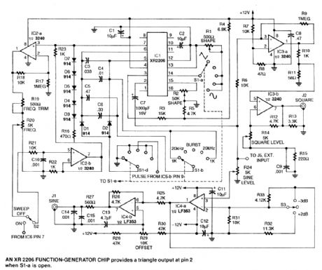
SWEEP_FUNCTION_GENERATOR_1
Published:2009/6/19 3:17:00 Author:May


Both IC2 and IC4 are Exar XR2206 monolithic function generators; IC4 functions as a ramp gen-erator, and IC2 functions as a generator of sine, triangular, and square waveforms. Dual operational amplifier IC1 produces a scaled, level-shifted ramp output that is capable of deflecting an oscillo-scope's horizontal sweep.Any frequency of interest along the horizontal axis of an oscilloscope that is coupled to this func-tion generator can be mgasured with an external frequency counter by manually tuning the function generator's VCO instead of sweeping it. The performance characteristics of the sweep/function gen-erator are summarized in the Table.The generator's sweep rate and frequency can be set by front-panel rotary six-position switches, Sweep Rate Switch S5 and Frequency Switch S2. The VCO control R30 manually tunes the VCO.Table 2 lists the sweep ranges of the function generator. Sweep ranges not covered in ranges 1 to 4 can be set up as required on positions 5 and 6. Selecting the VCO setting on the front panel toggle switch S4 permits tuning any fixed frequency within the total frequency range of the instrument with both frequency switch S2 and VCO control R30.The sweep rate or duration of the sweep ramp is selected by the rotary six-position Sweep Rate Switch S5. Table 3 lists the sweep rate durations for each of the six positions. Longer periods should be used for lower frequency sweeps. (View)
View full Circuit Diagram | Comments | Reading(4251)
GATE_DIP_OSCILLATOR_II
Published:2009/6/19 3:17:00 Author:May

Useful for measuring the resonant frequencies of antennas, tuned circuits, and also as a tuned detector, this circuit is a modem variation of the classic vacuum tube grid dip oscillator. It coupled the G.D.O. to a tuned circuit and caused RF energy to be absorbed by the unknown tuned ctrcutt when the G.D.O. frequency was the same as that of the tuned circuit in question. This showed as a dip in the meter reading. (View)
View full Circuit Diagram | Comments | Reading(2597)
FUNCTION_GENERATOR
Published:2009/6/19 3:07:00 Author:May
These three circuits make up an audio frequency function generator and can be individually used for custom applications. (View)
View full Circuit Diagram | Comments | Reading(0)
GATE_DiP_OSCILLATOR_I
Published:2009/6/19 3:00:00 Author:May

The typical dip meter is comprised of a tuning coil,RE oscillator,a detector,and a meter as shown in A.When the meter's tuning coil is coupled to a tuned circuit resonating at the same fre-quency as the GDM,the reading dips (C).The GDM's tuning coil can be coupled to the coaxial feed line of an antenna through a few(perhaps 2 to 3)turns of wire,and used to determine the antenna's resonant frequency(D). (View)
View full Circuit Diagram | Comments | Reading(1675)
DIGITAL_THREE_PHASE_WAVE_GENERATOR
Published:2009/6/19 2:51:00 Author:May

With a simple digital circuit, three-phase square waves can be produced from a single-phase square-wave signal source. The timing diagram shows that the second and third phases are 1200 and 2400 behind the first phase, respectively.The frequency range over which the three-phase outputs will occur is limited only by the capa-bility of the logic used. The output frequency is 1/6 of the input frequency. (View)
View full Circuit Diagram | Comments | Reading(761)
AUTO_BATTERY_ISOLATOR_CIRCUIT
Published:2009/6/19 2:39:00 Author:May

The diodes ensure that current can flow in both batteries from the altemator, but the main battery can't feed the accessory system, nor vice versa. (View)
View full Circuit Diagram | Comments | Reading(785)
555 8kV high voltage generater circuit
Published:2011/5/11 4:10:00 Author:May | Keyword: 555, 8kV, high voltage generater

This high voltage generator can generate stable high voltage above 8kV. Its circuit is simple. It is stable and reliable. This circuit includes step-down rectifier, voltage regulator circuit, 18kHz multivibrator type oscillator and booster transformer, etc. Its circuit is shown in diagram 24-32.Step-down rectifier consists of step-down transformer T1 and full bridge rectifier and filter capacitor C1, etc. The rectified 15V DC voltage passes three terminal regulator 7812 to regulated voltage and outputted +12V stable DC voltage, it can offer working voltage for IC2, VT1, etc.Astable multivibrator consits of 555 and R1, R2, C3, etc. Its oscilating frenquency is fc=1.44/(R1+2R2)C3Parameter shown in diagram is designed according to 18.5kHz. (View)
View full Circuit Diagram | Comments | Reading(1551)
10_Hz_TO_10_kHz_VCO_WITH_SQUARE_AND_TRIANGLE_WAVE_OUTPUTS
Published:2009/6/18 23:37:00 Author:May

View full Circuit Diagram | Comments | Reading(725)
SCHMITT_TRIGGER_SINE__SQUARE_WAVE_GENERATOR
Published:2009/6/18 23:36:00 Author:May

A sine wave input can produce a square wave output by this Schmitt trigger circuit based on a 555 IC. (View)
View full Circuit Diagram | Comments | Reading(4106)
VARIABLE_FREQUENCY_SQUARE_WAVE_GENERATOR
Published:2009/6/18 23:35:00 Author:May

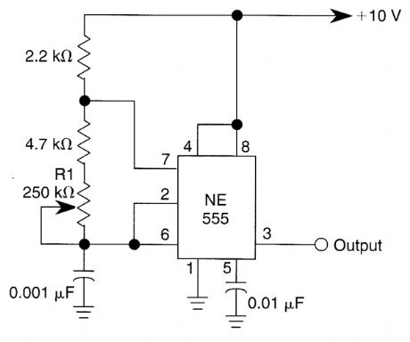
This simple square-wave generator produces a variable frequency output of 2800 Hz to 80 kHz with the values shown. Frequency is adjusted with potentiometer R1. (View)
View full Circuit Diagram | Comments | Reading(2011)
60_Hz_SQUARE_WAVE_GENERATOR
Published:2009/6/18 23:30:00 Author:May
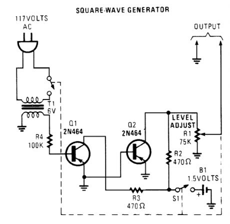
This generator circuit uses an overdriven amplifier to produce a 60-Hz square wave from the 60-Hz ac line. The circuit can be used in lineoperated applications as a clock source. (View)
View full Circuit Diagram | Comments | Reading(779)
SQUARE_WAVE_OSCILLATOR
Published:2009/6/18 23:28:00 Author:May

An Op amp with positive feedback generatesa square wave. The period ofthe oscillator is determined by R3 and C1.T=T1 + T2 ≈0.69×2 (R3C1) T1=T2 (View)
View full Circuit Diagram | Comments | Reading(1)
| Pages:143/195 At 20141142143144145146147148149150151152153154155156157158159160Under 20 |
Circuit Categories
power supply circuit
Amplifier Circuit
Basic Circuit
LED and Light Circuit
Sensor Circuit
Signal Processing
Electrical Equipment Circuit
Control Circuit
Remote Control Circuit
A/D-D/A Converter Circuit
Audio Circuit
Measuring and Test Circuit
Communication Circuit
Computer-Related Circuit
555 Circuit
Automotive Circuit
Repairing Circuit