Signal Processing
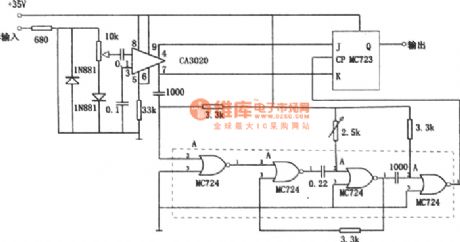
Digital frequency shift demodulator(CA3020、MC723、MC724)
Published:2011/7/18 20:22:00 Author:zj | Keyword: Digital, frequency shift, demodulator | From:SeekIC

As shown in the figure it is the digital frequency demodulation circuit. The circuit can be used in 1kHz to 10kHz frequency range, and can be demodulated to the 1% frequency offset. The input stage of the circuit is composed of wide band amplifier CA3020. The differential output is added to the J-K input end of J-K trigger. Gate circuit MC724 constitutes the monostable multivibrator. Monostable multivibrator timing cycle is equal to the center frequency of the half cycle. Input signal strobes trigger after being delayed by the monostable multivibrator.
Reprinted Url Of This Article:
http://www.seekic.com/circuit_diagram/Signal_Processing/Digital_frequency_shift_demodulatorCA3020-MC723-MC724.html
Print this Page | Comments | Reading(3)

Article Categories
power supply circuit
Amplifier Circuit
Basic Circuit
LED and Light Circuit
Sensor Circuit
Signal Processing
Electrical Equipment Circuit
Control Circuit
Remote Control Circuit
A/D-D/A Converter Circuit
Audio Circuit
Measuring and Test Circuit
Communication Circuit
Computer-Related Circuit
555 Circuit
Automotive Circuit
Repairing Circuit
Code: