
Signal Processing
Index 154
The auto-control ventilator circuit of 555
Published:2011/6/14 23:27:00 Author:Borg | Keyword: auto-control circuit

Figure 12-36 The auto-control circuit of ventilators The gas-sensitive element is fixed with MQ-N sensor, whichforms the gas detection circuit with RP1,R1 and C1; the thermistor of RT, C2 and RP3 form the temperature detection circuit. D1 and D2 form the logic circuit, VT1 is the e-switch, when the harmful gas content or the interior temperature is in the range of regulated values, VT1 is cut off and the 6-lead of the backward IC is in a 2/3VDD LEV, 555 is in a reset state,i.e 3-lead is in a low LEV, SCR is blocked and the motor M is still. (View)
View full Circuit Diagram | Comments | Reading(922)
The frequency splitter adjusted by the potentiometer (CC4013 and CH3130)
Published:2011/6/21 9:47:00 Author:Borg | Keyword: frequency splitter, potentiometer

In the circuit, the D/A converter switches the input data into the voltage, and the voltage is compared with the reference voltage set by the potentiometer, then the output of the comparator is fed back to the reset terminal of the comparator, finally, we get the split pulse. The working method of the circuit is different from that of the feedback splitter of traditional counter, although the traditional way is suitable for solid integer splitting, the constant isn't easy to adjust. This circuit is specially suitable for conditions that need to change the splitting constant in a wide range. (View)
View full Circuit Diagram | Comments | Reading(623)
The pulse widened device circuit of photoelectric couplers
Published:2011/6/28 7:47:00 Author:Borg | Keyword: widened device, photoelectric couplers

The pulse widened device of photoelectric couplers When we need to widen the narrow pulse, the figured circuit can be adopted. With the figured parameters, the pulse whose width is 3μs can be widened as the pulse of 1.2ms, as there is the passive feedback of the resistor of 100kΩ, so the output signal UA is more stable. (View)
View full Circuit Diagram | Comments | Reading(577)
The integrated electric ballast circuit of R2157 straight pipe type
Published:2011/7/6 1:14:00 Author:qqtang | Keyword: electric ballast, straight pipe
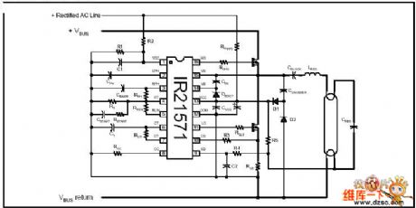
Figure: The integrated electric ballast circuit of R2157 straight pipe type (View)
View full Circuit Diagram | Comments | Reading(533)
Single-phase contact type variac voltage regulator circuit
Published:2011/7/6 2:26:00 Author:Christina | Keyword: Single-phase, contact type, variac, voltage regulator
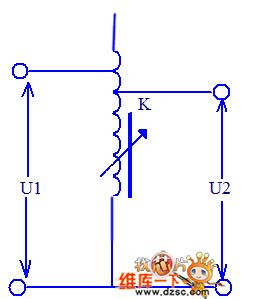
The Single-phase contact type variac voltage regulator circuit is as shown in the figure:
When the capacity of each variac is not enough, you can connect several variacs in parallel. In order to guarantee the equation of the secondary side voltages when it is operating and avoid to cause the potential difference, the adjustment of the parallel transformers must be synchronized. In addition, it needs an output port series reactor to evenly distribute the power. (View)
View full Circuit Diagram | Comments | Reading(907)
A precise constant temperature controller circuit without temperature jumping area
Published:2011/7/4 20:46:00 Author:Borg | Keyword: temperature controller, temperature jumping area
The be knots of Q1 and Q2 are used as the temperature sensor. The 2.5V highly stable Vref is provided by the precise regulated integrated circuit U3(TL431) as the reference input of the window voltage comparators (U2C,U2D) and difference amplifier (U1C). The connection of U1A and U1B is for debugging and the balance of the input impedance of the amplifier. The voltage follower U1D works as the buffer separator, which sends the temperature differential voltage Vd, which is amplified by U1C, to the non-inverting terminal of the voltage comparator U2B.
(View)
View full Circuit Diagram | Comments | Reading(760)
The temperature control circuit composed of the temperature sensor
Published:2011/7/6 1:21:00 Author:qqtang | Keyword: temperature control, temperature sensor
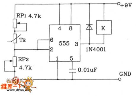
By adjusting RP1 and RP2, the temperature point can be preset, the 555 time-based circuit composes the Schmidt reversal phase circuit, the auto control is fulfilled by using the relay.
(View)
View full Circuit Diagram | Comments | Reading(1180)
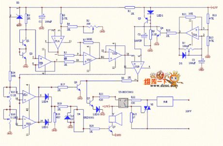
The temperature sensor auto control music play circuit
Published:2011/7/6 1:49:00 Author:qqtang | Keyword: temperature sensor, auto control
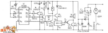
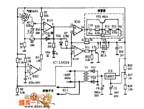
See as the figure, the circuit consists of the temperature sensor and the relay controlled fan motor circuit, temperature limit indicating circuit, music generating circuit and AC step-down circuit, etc. The core part is the TC621 temperature control integrated circuit.
(View)
View full Circuit Diagram | Comments | Reading(625)
The strain meter circuit of the internal half-bridge net of the signal modulator
Published:2011/7/6 1:05:00 Author:qqtang | Keyword: strain meter, half-bridge net, signal modulator
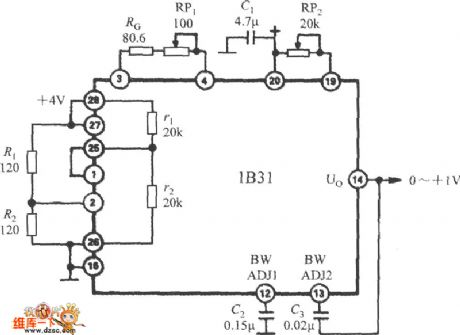
The the strain meter circuit of the internal half-bridge net of the wide band stress signal modulator 1B31 is shown as above.
(View)
View full Circuit Diagram | Comments | Reading(695)
The auto cooker hood circuit (01)
Published:2011/6/19 19:52:00 Author:qqtang | Keyword: cooker hood
View full Circuit Diagram | Comments | Reading(941)
The 555 darkroom timer circuit (3)
Published:2011/6/14 2:44:00 Author:TaoXi | Keyword: darkroom, timer
Related components PDF download:
NE5553DG6
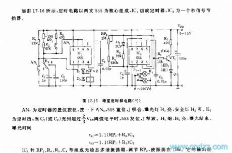
As the figure 17-16 shows, the timer circuit uses two 555 as the core, the timer is composed of the IC1, IC2 is the
second signal metronome.
AN1 is the timer's set button, if you press AN1, the 555 sets, the J closes, the exposure light H1 turns on and the safe light H2 turns off. K1 is the timing gear, when C1 or C2 has the voltage level of more than 2/3VDD, 555 resets, J releases. H1 turns off, H2 turns on, the exposure is over.
The exposure time: td1=1.1(RP1+R2)C1 td2=1.1(RP1+R2)C2
The astable multivibrator is composed of the IC2, RP2,R4,R5 and the C4.etc, By adjusting RP2, you can make the oscillation in the 1Hz. It's output drives the red LED to turn on through VT1.
(View)
View full Circuit Diagram | Comments | Reading(570)
Numerical control triangle wave-square wave generator circuit
Published:2011/6/27 2:51:00 Author:TaoXi | Keyword: Numerical control, triangle wave, square wave, generator circuit
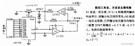
Numerical control triangle wave-square wave generator circuit: the integrator is composed of the N1, it integrates the output current of the D/A converter to change the output voltage linearly; the voltage comparator is composed of the N2, its output voltage is limited by the two-way voltage diode 2DW7from +6.5Vto -6.5V.
(View)
View full Circuit Diagram | Comments | Reading(866)
Quartz crystal rectangular wave oscillator circuit
Published:2011/6/27 2:51:00 Author:TaoXi | Keyword: Quartz crystal, rectangular wave, oscillator circuit

The quartz crystal rectangular wave oscillator circuit is mainly used in the new digital system clock-pulse generator. When the quartz crystal of this circuit is in the resonant state, the transmission amount is the largest, now the harmonic oscillation rate of the quartz crystal is the crystal's harmonic oscillation rate. Because ofthe high output impedance of LM111 and the isolation effect of C2, so the load of the quartz crystal is very small. The stability of the oscillation frequency is high. The circuit has the 100KHz rectangle wave output.
(View)
View full Circuit Diagram | Comments | Reading(2214)
Time Relay (the 3rd)
Published:2011/7/5 2:27:00 Author:Felicity | Keyword: Time Relay (the 3rd)
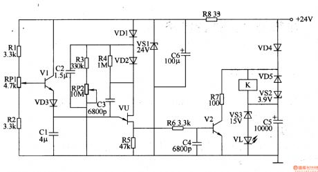
Work of the circuit
The circuit consists of regulator filter circuit, the delay charge and discharge circuit and relay control circuits. (It is showed in the picture 8-137.)
Regulator filter circuit consists of Resistor R8, zener diode VS1 and filter capacitor C6.
The delay charge and discharge circuit consists of Resistors Rl-R5, capacitor RPl and RP2, transistor Vl, capacitors Cl-C3, diodes VDl-VD3 and single-junction transistor VU.
Relay control circuits consists of resistors R6 and R7, capacitors C4 and C5, diode VD4 and VD5, voltage regulator diode VS2 and VS3, the transistor V2, LED VL and relays K. (View)
View full Circuit Diagram | Comments | Reading(598)
Time Relay (the 2nd)
Published:2011/7/5 2:28:00 Author:Felicity | Keyword: Time Relay (the 2nd)

Work of the circuit
The circuit consists of +12V power circuit, monostable circuit and relay control circuits. (It is showed in the picture 8-136.)
Power circuit consists of power transformer T, rectifier diode VDl, VD2, three-terminal voltage regulator integrated circuit ICl and filter capacitor Cl, C2.
Monostable circuit consists of potentiometer RP, diodes VD3, capacitors C3, C4, time-base integrated circuit IC2 and the normally closed contact relay Kl.
Relay control circuits consists of resistors Rl, R2, relay Kl, K2, diodes VD4 and LED VL. (View)
View full Circuit Diagram | Comments | Reading(586)
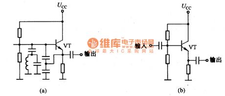
The emitting circuit composed of SF04E and SF04B
Published:2011/6/25 5:26:00 Author:Borg | Keyword: emitting circuit
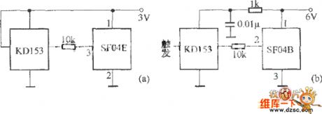
Figure: The emitting circuit composed of SF04E and SF04Ba) indicates the remote emitting circuit composed of SF04E, its coupled reception circuit can be SJ04H components; b) indicates the remote emitting circuit composed of SF04B, which can be coupled as the reception circuit with SJ04E. (View)
View full Circuit Diagram | Comments | Reading(519)
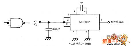
Signal generator simplified with MC4024P circuit
Published:2011/7/4 6:45:00 Author:John | Keyword: Signal Generator
View full Circuit Diagram | Comments | Reading(773)
Oscillation circuit of the emitter follower
Published:2011/6/30 13:01:00 Author:Sophia | Keyword: Emitter follower, Oscillation
(View)
View full Circuit Diagram | Comments | Reading(1065)
Lighting and signal basic circuit diagram of Beijing "City Cat People" 2020SG puddle jumper
Published:2011/6/30 12:12:00 Author:Sophia | Keyword: Beijing "City Cat People" 2020SG puddle jumper, Lighting, signal basic circuit
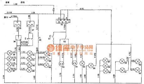
1. integrated switches Integrated switch on the steering column below the steering wheel, its features are: headlight dimmer, overtaking, turning, hazard warning switch gears and horn buttons, and it can rely on the steering wheel back body to automatically turn off the lights. 2. the fog lamp switch Left and right side of front bumper of BJ20205G has two fog lamps 29, 30, to open the fog lamp switch 31 can open the fog lights. 3. lighting switch Light switch 5O belongs to the JKlO1 type, there are three positions, namely close, l block, D block. (1) Ⅰ gear: it used to connect to front signal light 60, 61, tail lights 62 and 63, instrument lamp 57,58 and 59, license plate lights 56. (2) Ⅱ gear: In addition to accessing a variety of lights connecting to I blocking, it connects the headlamps 53, 54. simmer switch 52 chooses the distance light. Overtaking signal is sent by the switch 51. (View)
View full Circuit Diagram | Comments | Reading(1103)
1-20MHz quartz crystal oscillator circuit
Published:2011/7/4 4:12:00 Author:Christina | Keyword: 1-20MHz, quartz crystal, oscillator

The quartz crystal oscillator circuit which is composed of the quartz crystal resonator and the coupling capacitance of the multivibrator is as shown in figure 1. This oscillation frequency of this circuit depends on the resonant frequency of the quartz crystal, and it has nothing to do with the R, C components of the circuit, you just need to change the quartz crystal resonator, so you can select the oscillation frequency of the oscillator in the range of 1-2OMHz.
Figure 1 The 1~2OMHz quartz crystal oscillator circuit
(View)
View full Circuit Diagram | Comments | Reading(3029)
| Pages:154/195 At 20141142143144145146147148149150151152153154155156157158159160Under 20 |
Circuit Categories
power supply circuit
Amplifier Circuit
Basic Circuit
LED and Light Circuit
Sensor Circuit
Signal Processing
Electrical Equipment Circuit
Control Circuit
Remote Control Circuit
A/D-D/A Converter Circuit
Audio Circuit
Measuring and Test Circuit
Communication Circuit
Computer-Related Circuit
555 Circuit
Automotive Circuit
Repairing Circuit