Signal Processing
The 555 darkroom timer circuit (3)
Published:2011/6/14 2:44:00 Author:TaoXi | Keyword: darkroom, timer | From:SeekIC

Related components PDF download:
NE5553DG6
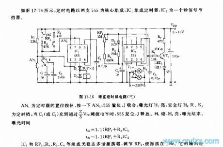
As the figure 17-16 shows, the timer circuit uses two 555 as the core, the timer is composed of the IC1, IC2 is the
second signal metronome.
AN1 is the timer's set button, if you press AN1, the 555 sets, the J closes, the exposure light H1 turns on and the safe light H2 turns off. K1 is the timing gear, when C1 or C2 has the voltage level of more than 2/3VDD, 555 resets, J releases. H1 turns off, H2 turns on, the exposure is over.
The exposure time: td1=1.1(RP1+R2)C1 td2=1.1(RP1+R2)C2
The astable multivibrator is composed of the IC2, RP2,R4,R5 and the C4.etc, By adjusting RP2, you can make the oscillation in the 1Hz. It's output drives the red LED to turn on through VT1.
Reprinted Url Of This Article:
http://www.seekic.com/circuit_diagram/Signal_Processing/The_555_darkroom_timer_circuit_3.html
Print this Page | Comments | Reading(3)

Article Categories
power supply circuit
Amplifier Circuit
Basic Circuit
LED and Light Circuit
Sensor Circuit
Signal Processing
Electrical Equipment Circuit
Control Circuit
Remote Control Circuit
A/D-D/A Converter Circuit
Audio Circuit
Measuring and Test Circuit
Communication Circuit
Computer-Related Circuit
555 Circuit
Automotive Circuit
Repairing Circuit
Code: