
Signal Processing
Index 156
oscillator composed of gate circuit circuit
Published:2011/6/26 8:36:00 Author:Fiona | Keyword: composed of gate circuit
View full Circuit Diagram | Comments | Reading(506)
Parallel type crystal oscillator circuit
Published:2011/6/26 9:01:00 Author:Fiona | Keyword: Parallel type, crystal
Among this circcuit, the resistors R1,2 and resistors R5, R6, R7 are the DC bias component of the transistors VT1 and VT2.High-frequency choke coil L2 offers the DC path to the the collector current of the oscillation tube VT1. C2 is the blocking capacitors.C3, C7 are the exchange bypass capacitor which make the emitter of the VTl in exchange zero potential,but the DC-bit is not zero.The inductor L1, capacitor c6,resistor R 3 improve the power supply filter circuit,whose role is to reduce ripple voltage to increase the DC component. Slightly adjustable capacitors can change the size of the coupling signal.
(View)
View full Circuit Diagram | Comments | Reading(512)
555 tone-changing audio circuit
Published:2011/6/15 22:39:00 Author:TaoXi | Keyword: 555, tone-changing, audio
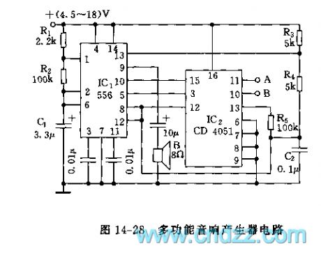
As the figure 14-29 shows, the circuit uses the two bipolar type 555s as the core, the astable multivibrator is composed of the IC1 and RP1, R1, C1, f1=1.44/(RP1+2R1)C1, the frequency of figure parameters is about 1Hz. The output of IC1 adds to the control port of IC2 through the R2 and C2 integral circuits to make the IC2 to become a controllable multivibrator, the speaker outputs the tone-changing audio with the frequency of dozens of Hertz and thousands of Hertz.
(View)
View full Circuit Diagram | Comments | Reading(521)
The 555 touch audio circuit
Published:2011/6/16 2:18:00 Author:TaoXi | Keyword: 555, touch audio
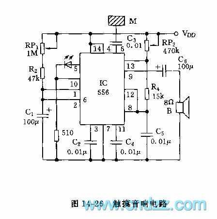
As the figure 14-26 shows, the monostable trigger and the multivibrator are composed of a double-time base 556 and some RC components. When the hand touches the sheetmetal M, the induction signal of human body adds to the trigger port pin-6 of IC through C3, so the circuit is triggered, the output port pin-5 of this time base circuit is from the low level to the high level. Because the astable multivibrator's time base circuit reset port pin-10 has the high electrical level, so the oscillator starts working, the oscillation frequency is between 300~4500Hz, so the speaker sends out the sound. When the monostable circuit is triggered, the power supply voltage charges to C1 through RP1 and R2, the delay time td=1.1(RP1+R2)C1.
(View)
View full Circuit Diagram | Comments | Reading(535)
555 fridge compressor work timer circuit
Published:2011/6/16 2:53:00 Author:TaoXi | Keyword: fridge, 555, compressor, work, timer
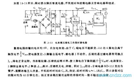
As the figure 13-13 shows, the displayer is composed of the step-down rectifier circuit, the boot delay and control circuit and the audio circuit.etc.
The output voltage of the rectifier circuit is about 8V, at beginning, because the voltage of C3 can not be changed, so the electric potential of 555's pin-6 is higher than the trigger electrical level 2/3VDD to reset the circuit, the pin-3 outputs the low electrical level, the relay J will not work. The compressor gets power through the relay normally closed contact point J1-1 to work. When the fridge is broken, the compressor will not stop working, when the electric potential of pin-2 is lower than 1/3VDD, the circuit sets, pin-3 has the high electrical level, J releases, J1-1 cuts off, so the compressor has no power and stops working.
(View)
View full Circuit Diagram | Comments | Reading(754)
555 fridge door-closing reminder circuit (2)
Published:2011/6/16 6:20:00 Author:TaoXi | Keyword: 555, fridge, door-closing, reminder
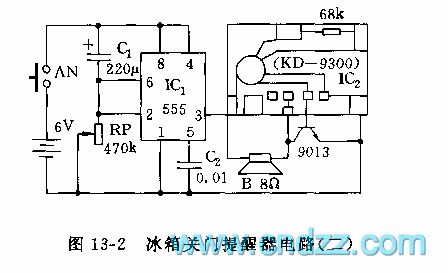
As the figure 13-2 shows, the reminder is composed of the monostable delay circuit which is composed of the 555, C1, RP and a KD-9300 music IC2. When you open the door, the switch AN is pressed, the 6V power adds to the 555, because the voltage of capacitor C1 can not be changed, so pin-2 has the high electric potential to make the 555 to output the low electrical level. After the delay time of 0 to 2 minutes, the circuit sets, IC2 gets the power to send out the sound of music. After you close the door, AN is unclinched, you can change the delay time by adjusting RP.
(View)
View full Circuit Diagram | Comments | Reading(549)
AN3788S switch pulse generating integrated circuit
Published:2011/6/30 6:47:00 Author:Christina | Keyword: switch, pulse, generating integrated circuit

The AN3788S switch pulse generating integrated circuit is produced by the Panasonic company that can be used in the cameras such as th Panasonic NV-M8000 camera.etc.
1.Features
The AN3788S is composed of the switch pulse generator, the error voltage comparator, the compare pulse inverter and other subsidiary circuits. The internal circuit block diagram is as shown in figure 1.
Figure 1 The internal circuit block diagram and the typical application circuit of the AN3788S
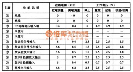
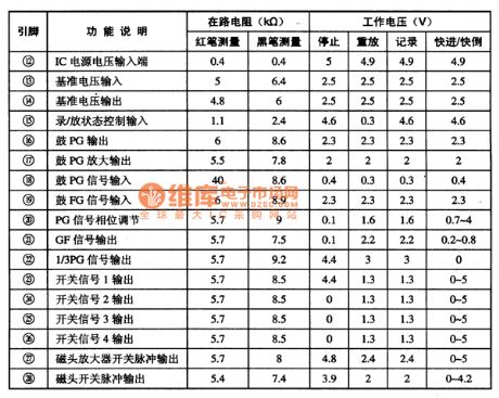
2.Pin functions and data
The AN37885 uses the 28-pin dual-row DIP package, the pin functions and data are as shown in table 1.
Table 1 The pin functions and data of the AN37885
3.Typical application circuit
The typical application circuit of the AN3788 is as shown in figure 1. (View)
View full Circuit Diagram | Comments | Reading(536)
AN33215S brightness signal processing integrated circuit
Published:2011/6/30 7:11:00 Author:Christina | Keyword: brightness signal, processing, integrated circuit
The AN33215S brightness signal processing integrated circuit is produced by the Panasonic company that can be used in the Panasonic AN-M series cameras.
1.Features
The AN3215S's main function: it amplifies and modulates the FM brightness signal which is sent from the video magnetic head amplifier when it is replaying, and it reverts the FM brightness signal to the brightness signal, then the brightness signal composes of the video signal with the chroma signal. When it is recording, it AGC amplifies, black and white cute, and clamps the video signal to change it into the FM signal, this FM signal adds to the magnetic head amplifier to supply the recording signal for the video magnetic head.
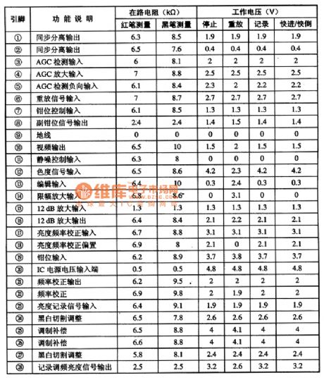
2.Pin functions and data
The AN3215S uses the 28-pin dual-row plastic structure, the pin functions and data are as shown in table 1.
Table 1 The pin functions and data of the AN3215S
3.Typical application circuit
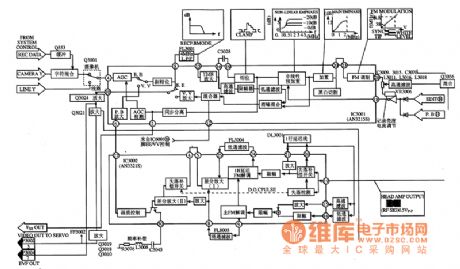
The internal circuit block diagram and the typical application circuit are as shown in figure 1.
Figure 1 The internal circuit block diagram and the typical application circuit of the AN3215S
(View)
View full Circuit Diagram | Comments | Reading(492)
488kHz signal generator and frequency divider circuit
Published:2011/6/18 21:49:00 Author:Nancy | Keyword: 488kHz, signal generator, frequency divider
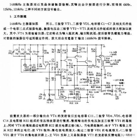
1488kHz master oscillator uses quartz crystal resonator to stabilize frequency, the output is divided by the frequency divider to obtain three different square wave outputs which are 4kHz, 12kHz and 124kHz.
Working principle:1488kHz master oscillator is shown as the circuit. Triode VT1, diode VD1, capacitor C1-C7 and related components form a capacitance connecting three point type oscillator circuit. The oscillating voltage is amplified by the amplifer composed by triode VT2-VT5 and related components. VT4 is emitter output which is featured with high input impedance, low output impedance, and increases the backward stage with load capacity and stabilize the forward stage oscillating signal. Transformer T outputs 1488kHz signal frequency after amplified. (View)
View full Circuit Diagram | Comments | Reading(681)
The releasing interfere and preventing thief dozen circuit
Published:2011/6/30 3:19:00 Author:Fiona | Keyword: The releasing interfere, preventing thief dozen

The releasing interfere and preventing thief dozen circuit is shown as below,T,R is the phone into the line side,telephone is connected to the A, B-side.When the user uses the telephone,the burglar alarm does not work. When a theft or fight occurs, the line voltage reduces,transistor V1 is cut-off, base V2 obtains the high potential to be conducted,V3 is conducted too,so that there is output voltage on the stabilivolt VD3,the oscillator has electricity,the oscillator has electricity through the C6 input,the C6 output oscillation voltage to the telephone line,disturbs the pirates caller.
(View)
View full Circuit Diagram | Comments | Reading(586)
Hands-free telephone terminal circuit
Published:2011/6/29 1:49:00 Author:Fiona | Keyword: Hands-free telephone terminal

Conference call terminal is made by the hands-free phone chips, high-quality hands-free phone chips MC34118 ensure the properties of the machines is reliable,elements connected way and the parameter selection of the part pins in the circuit components in the connection and parameters chose retaining the original MC34118 basic connection,however,it makes some change at microphone input, speaker output,power supply and telephone line connection to meet the needs to listen to teleconference.
(View)
View full Circuit Diagram | Comments | Reading(3724)
Piezoelectric high level automatic control and alarming circuit
Published:2011/6/30 10:51:00 Author:John | Keyword: automatic control

The shown circuit consists of the piezoelectric material level sensor, relay control mechanical circuit, analog voice circuit and AC buck rectifier circuit. When the material level rises to the high material level, the circuit can be issued for a given analog sound and also cut off the power supply of the feeding equipment. Then the feeding process stops in order to ensure safe operation. IC1 is a piezoelectric material level sensing circuit, which consists of self-excited oscillator, rectifier circuit, voltage comparator circuit and output stage of the open circuit.
(View)
View full Circuit Diagram | Comments | Reading(786)
Heart Rhythm Tester (the 4th)
Published:2011/6/23 21:40:00 Author:Felicity | Keyword: Heart Rhythm Tester (the 4th)
Work of the circuit
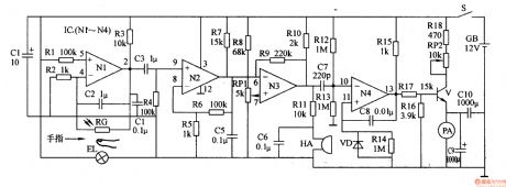
The circuit consists of photo electricity testing circuit, signal amplifying circuit, buzzer driving circuit and current indicating circuit. (It is shows in picture 9-56.)
When you do the test, put your finger between EL and RG. Some lights of EL go through the finger and shines on RG. RG produces sensitive signal. The signal is amplified by N1-N3 and separates into two parts. One drive HA makes the buzzer work. And the other one goes through ammeter and indicates the current value. The current value increases by the rate of heart beating.
Change the value of RP1 to change the accuracy. Change the value of RP2 to change the testing scope. (View)
View full Circuit Diagram | Comments | Reading(646)
Heart Rhythm Tester (the 3rd)
Published:2011/6/23 21:39:00 Author:Felicity | Keyword: Heart Rhythm Tester (the 3rd)
Work of the circuit
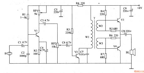
The circuit consists of sensor B, pre-amplifying circuit, low frequency amplifying circuit and capacity amplifying circuit. (It is shows in picture 9-55.)
When you use the tester, put it on the heart area. Use hands to fix it. B changes the sound of hearting beating into electronic signal. The electronic signal is pre-amplified by V1, sound controlled by RP2, low frequency amplified by V2 and capacity amplified by V3, V3. The amplifier BL will play the amplified sound of heart beating. (View)
View full Circuit Diagram | Comments | Reading(548)
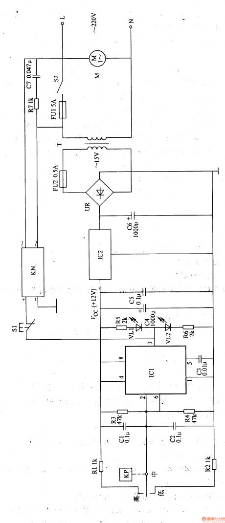
Electric Medical Attracting Controlling Circuit (the 3rd)
Published:2011/6/25 5:22:00 Author:Felicity | Keyword: Electric Medical Attracting Controlling Circuit (the 3rd)
Work of the circuit
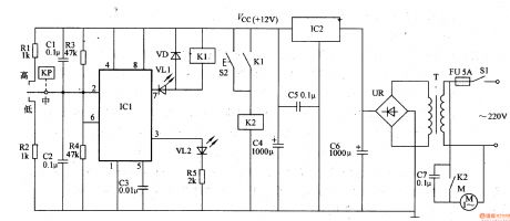
The circuit consists of power circuit, negative pressure testing circuit, bistable state circuit, VL indicating circuit and controlling execution circuit. (It is showed in picture 9-45.)
Turn on the power switch S2. The 220V AC voltage supplies +12V working power to bistable state circuit and controlling execution circuit.
When the circuit just starts working, the gas in the negative pressure bottle is of normal state. The internal outputting circuit of KP is closed and VL1 is lightened. At the same time, M starts working normally. When the negative pressure reaches to a certain value, M stops working. At the same time VL2 is lightened and VL1 is turned off. When the negative pressure is lower than a certain value, M starts working immediately.
S2 is the manual button. Press S1 and M starts working. Relax S2 and M stops working. (View)
View full Circuit Diagram | Comments | Reading(491)
Electric Medical Attracting Controlling Circuit (the 2nd)
Published:2011/6/25 5:20:00 Author:Felicity | Keyword: Electric Medical Attracting Controlling Circuit (the 2nd)
Work of the circuit
The circuit consists of power circuit, negative pressure testing circuit, bistable state circuit, working condition indicating circuit and controlling execution circuit. (It is showed in picture 9-44.)
Turn on the power switch S2. The 220V AC voltage supplies +12V working power to IC. When S2 is just turned on, the gas in the negative pressure bottle is of normal state. The internal outputting circuit of KP is closed and VL1 is lightened. When the negative pressure reaches to a certain value, M stops working. At the same time VL2 is lightened and VL1 is turned off. S1 is the manual button. Press S1 and M starts working. Relax S1 and M stops working. (View)
View full Circuit Diagram | Comments | Reading(477)
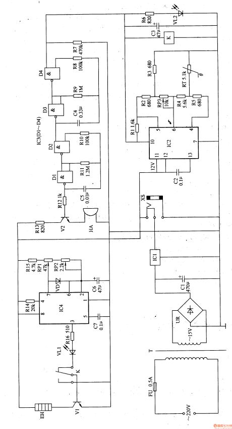
Magnetism Pulse Therapeutic Equipment (the 1st)
Published:2011/6/28 7:48:00 Author:Felicity | Keyword: Magnetism pulse Therapeutic Equipment (the 1st)
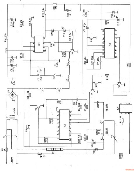
Work of the circuit
The circuit consists of power circuit, timing circuit, sound indicating circuit, magnetism pulse controlling circuit and heating controlling circuit. (It is showed in picture 9-15.)
Turn on power switch S1. The 220V AC voltage is adjusted and produces +15V voltage. It separates in to two parts. One is supplied to sound indicating circuit and magnetism pulse controlling circuit. While the other one is changed into 9V voltage and IC2 and KN.
The regular time is 60min. turn on the power and EH makes sounds. When the regular time is over, EH stops working and HA makes sound.
When EH is working, the temperature increases as well as the value of RT. When it reaches a certain degree, EH stops working. So the temperature decreases and EH starts to work again. This process is repeated until the regular time is over. (View)
View full Circuit Diagram | Comments | Reading(491)
Electronic Weight Instrument (the 2nd)
Published:2011/6/25 5:28:00 Author:Felicity | Keyword: Electronic Weight Instrument (the 2nd)
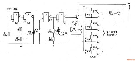
Work of the circuit
The circuit consists of OSC A, OSC B and step-up circuit. (It is showed in picture 9-37.)
OSC A is used to produce signal of low frequency to control OSC B. change the value of RP1 to change the rate of the signal of low frequency.
OSC B is under the control of OSC A. It can produce pulse signal string of low frequency. The signal is amplified and changed by the step-up circuit. It produces pulse voltage of low frequency on W2-W5. The voltage is adjusted by RP2-RP5. Then it is added on the proper part of body by poles.
(View)
View full Circuit Diagram | Comments | Reading(511)
Piles Therapeutic Equipment (the 2nd)
Published:2011/6/28 7:59:00 Author:Felicity | Keyword: Piles Therapeutic Equipment (the 2nd)
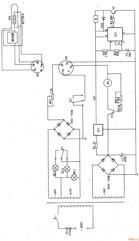
Work of the circuit
The circuit consists of power circuit, heating circuit, indicating circuit, vibration circuit and timing circuit. (It showed in picture 9-25.)
Turn on the power switch S. the 220V voltage is reduced by T. it then produces 36V, 6.3V and 10V AC voltage. When V1 is transmitted, it exports driving voltage from the poles. The voltage is added to EH and makes EH starts heating. Change the value of RP2 to change the value of V1, outputting voltage and outputting current. In that way the heating temperature of EH is changed.
The vibration heating probe consists of vibration and EH. The internal time is 4-5s. When S is turned on, HL1 shines. When the vibration works, HL2 shines. When the vibration stops working, the HL3 shines.
(View)
View full Circuit Diagram | Comments | Reading(447)
Piles Therapeutic Equipment (the 1st)
Published:2011/6/28 7:58:00 Author:Felicity | Keyword: Piles Therapeutic Equipment (the 1st)
Work of the circuit
The circuit consists of power circuit, temperature controlling circuit, sound warning circuit and pulse heating circuit. (It showed in picture 9-24.)
The 220V AC voltage supplies 12V DC working voltage to the whole circuit. The low frequency OSC consists of IC4 and the other parts around. The low frequency pulse signal is outputted from pin 3 of IC4. The signal makes V 1 and EH works with pause. The range of temperature is 37-45℃. If the temperature is higher than 45℃, the high level is exported from pin 10 of IC2. The high level is adjusted and drives HA to make warning sound.
When you use the machine, put the medicine on the probe and put it into the anus. Choose the proper temperature to make it work. (View)
View full Circuit Diagram | Comments | Reading(613)
| Pages:156/195 At 20141142143144145146147148149150151152153154155156157158159160Under 20 |
Circuit Categories
power supply circuit
Amplifier Circuit
Basic Circuit
LED and Light Circuit
Sensor Circuit
Signal Processing
Electrical Equipment Circuit
Control Circuit
Remote Control Circuit
A/D-D/A Converter Circuit
Audio Circuit
Measuring and Test Circuit
Communication Circuit
Computer-Related Circuit
555 Circuit
Automotive Circuit
Repairing Circuit