Signal Processing
555 game timer circuit
Published:2011/6/13 23:24:00 Author:nelly | Keyword: Game, timer | From:SeekIC


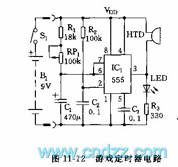
As shown in the figure 11-12, the monostable delay circuit is composed of 555 and R1, RP1, C1, R2, C2. the 2 foot of trigger terminal is connected to the joint point of R2, C2, when it is connected to power supply, the 2 foot has a negative pulse which the level is ground, it can set the circuit, the 3 foot is high level, LED turns on. At the same time, C1 is charged by R1, RP1, when C1's voltage is charged to 2/3 VDD of 6 foot's threshold value level, 555 is reset, the 3 foot is low level, LED turns off, buzzer HTD phonates, it shows that the timing time is reached. The timing time td=1.1(R1+RP1)C1. The td of indicative parameter is adjustable in the range of 10s~60s, it can be previously set according to the needs of game.
Reprinted Url Of This Article:
http://www.seekic.com/circuit_diagram/Signal_Processing/555_game_timer_circuit.html
Print this Page | Comments | Reading(3)

Article Categories
power supply circuit
Amplifier Circuit
Basic Circuit
LED and Light Circuit
Sensor Circuit
Signal Processing
Electrical Equipment Circuit
Control Circuit
Remote Control Circuit
A/D-D/A Converter Circuit
Audio Circuit
Measuring and Test Circuit
Communication Circuit
Computer-Related Circuit
555 Circuit
Automotive Circuit
Repairing Circuit
Code: