Signal Processing
Voltage Regulator (the 3rd)
Published:2011/7/16 0:37:00 Author:Felicity | Keyword: Voltage Regulator | From:SeekIC
Work of the circuit
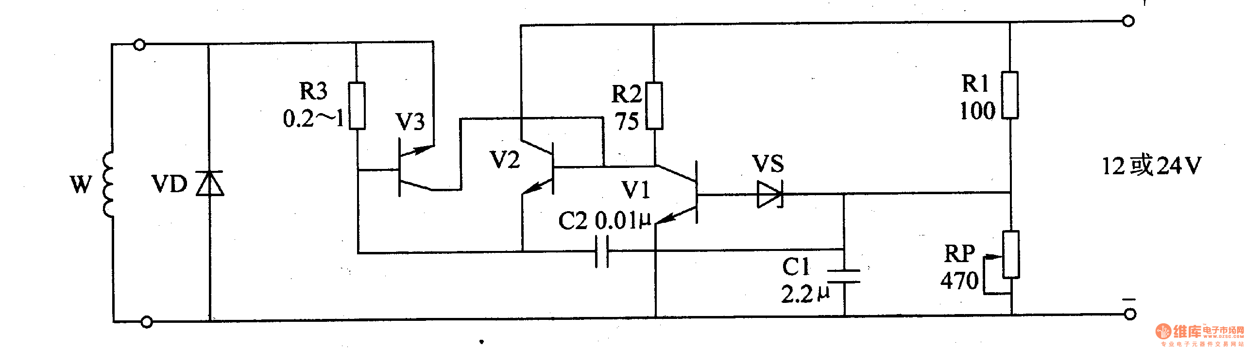
The circuit consists of automatic voltage regulation circuit and over-current protection circuit. (It is showed in picture 7-143.)
Automatic voltage regulation circuit consists of Resistors R2, R3, potentiometer RP, capacitor Cl, C2 and Zener diode VS.
Over-current protection circuit consists of Diode VD, resistor R3 and transistor V3.
When the charging voltage of AC electric generator is less than the least value, VS and V1 is cut-off. The charging voltage of AC electric generator is increasing. Here the voltage charges the battery under the certain voltage. When the exporting voltage reaches the highest value, VS is transmitted. The exporting voltage of the motor is decreasing. When the voltage reaches the lowest value, the voltage begins to increase again. In this way, the exporting voltage of the motor is in the scope of 14-14.5 V.
When the working current of V2 is regular, V3 is cut-off. Change the value of RP to change the scope of regulation.
.
Reprinted Url Of This Article:
http://www.seekic.com/circuit_diagram/Signal_Processing/Voltage_Regulator_the_3rd.html
Print this Page | Comments | Reading(3)

Article Categories
power supply circuit
Amplifier Circuit
Basic Circuit
LED and Light Circuit
Sensor Circuit
Signal Processing
Electrical Equipment Circuit
Control Circuit
Remote Control Circuit
A/D-D/A Converter Circuit
Audio Circuit
Measuring and Test Circuit
Communication Circuit
Computer-Related Circuit
555 Circuit
Automotive Circuit
Repairing Circuit
Code: