Position: Home > Circuit Diagram > Signal Processing > Orthogonal FM demodulation circuit with CA3098
Signal Processing
Orthogonal FM demodulation circuit with CA3098
Published:2011/7/17 22:26:00 Author:zj | Keyword: Orthogonal, FM demodulation circuit | From:SeekIC

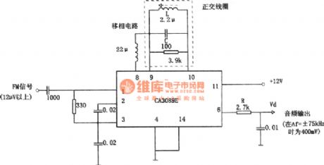
As shown in the figure thecircuit is 10.7MHz LC FM orthogonal demodulation circuit. Integrated circuit CA3089E in the diagram contains positive frequency amplifying circuit. If access ceramic filter ( lumped parameter filter)in the first level, it consists entirely FMdischarge circuit. Limiterworks whenthe input is greater than 12μV. AM differential ratio is 55dB. The output endRC is a de-emphasis circuit.
Reprinted Url Of This Article:
http://www.seekic.com/circuit_diagram/Signal_Processing/Orthogonal_FM_demodulation_circuit_with_CA3098.html
Print this Page | Comments | Reading(3)

Article Categories
power supply circuit
Amplifier Circuit
Basic Circuit
LED and Light Circuit
Sensor Circuit
Signal Processing
Electrical Equipment Circuit
Control Circuit
Remote Control Circuit
A/D-D/A Converter Circuit
Audio Circuit
Measuring and Test Circuit
Communication Circuit
Computer-Related Circuit
555 Circuit
Automotive Circuit
Repairing Circuit
Code: