Signal Processing
Cumulative Timer
Published:2011/7/4 10:20:00 Author:Felicity | Keyword: Cumulative Timer | From:SeekIC

work of the circuit
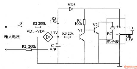
The circuit consists of resistor R1-R4, capacitor C, diode VD1-VD5, transistor V1, V2 and the crystal OSC BC. (It is showed in picture 8-144.)
Turn on the power switch of the electronic instrument and the 220V voltage is limited by R1 and R2 and rectified by VD1-VD4. It produces 2.07V DC voltage on C. The timing begins. When the power switch of the electronic instrument is turned off, the voltage on C disappears. The frequency division circuit stops vibrating. But the frequency division circuit remains in the condition. When you turn on S next time, it begins to time again.
Reprinted Url Of This Article:
http://www.seekic.com/circuit_diagram/Signal_Processing/Cumulative_Timer.html
Print this Page | Comments | Reading(3)

Article Categories
power supply circuit
Amplifier Circuit
Basic Circuit
LED and Light Circuit
Sensor Circuit
Signal Processing
Electrical Equipment Circuit
Control Circuit
Remote Control Circuit
A/D-D/A Converter Circuit
Audio Circuit
Measuring and Test Circuit
Communication Circuit
Computer-Related Circuit
555 Circuit
Automotive Circuit
Repairing Circuit
Code: