Signal Processing
Voltage Regulator (the 1st)
Published:2011/7/7 9:46:00 Author:Felicity | Keyword: Voltage Regulator, the 1st | From:SeekIC
Work of the circuit
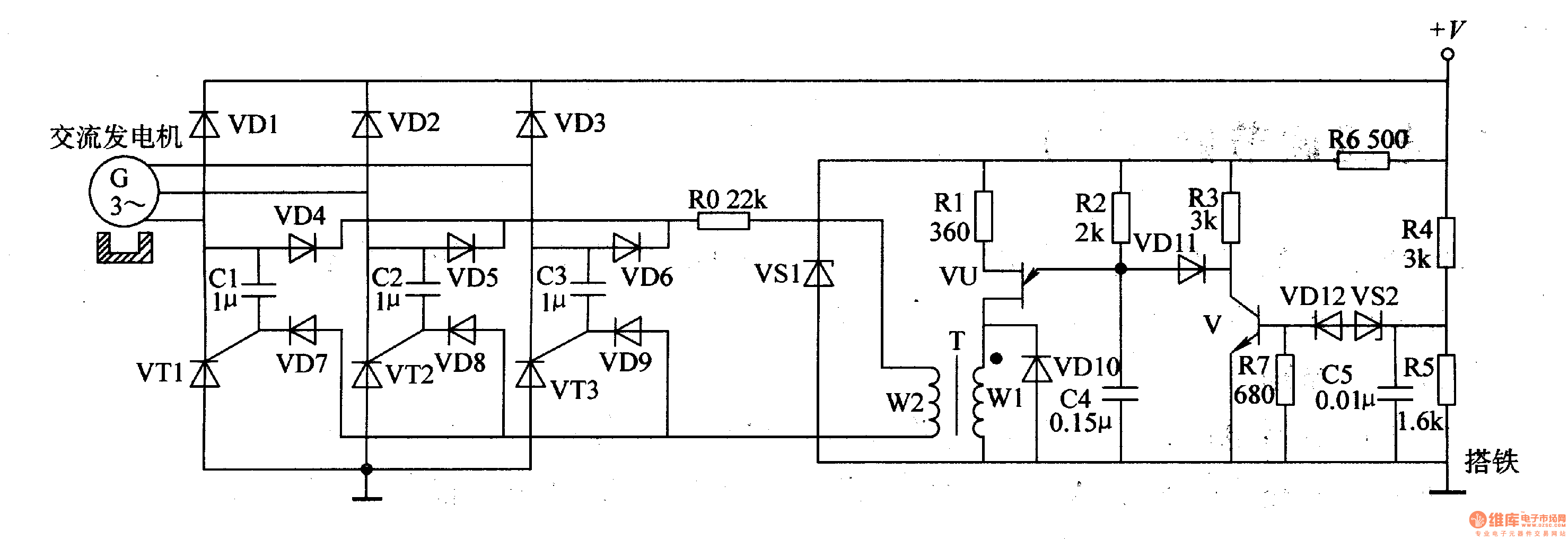
The circuit consists of sampling detection control circuit and relaxation oscillator circuit. (It is showed in picture 7-141.)
Sampling detection control circuit consists of resistors R3-R7, capacitor C5, voltage regulator diode VSI, VS2, diodes and transistors V VDl2.
Relaxation oscillator circuit consists of resistors Rl, R2, capacitor C4, diode VDlO, single-junction transistors VU and isolation transformer T.
Three-phase alternating generator exports pulsating DC voltage +V. The voltage is adjusted by R4 and R5 and added to the negative pole of VS2. The voltage separates into two parts. One is limited by R6 and works as the working voltage of sampling detection control circuit and relaxation oscillator circuit. C4 is charging by R2. When the pressure over C4 reaches the highest value of VU, VU is transmitted. At this time C4 is discharging through VU. When the voltage over C4 is lower than a certain value, C4 begins to charge and discharge. The process repeats and the relaxation oscillator circuit is under the condition of oscillating. The rectifier exports current.
Reprinted Url Of This Article:
http://www.seekic.com/circuit_diagram/Signal_Processing/Voltage_Regulator_the_1st.html
Print this Page | Comments | Reading(3)

Article Categories
power supply circuit
Amplifier Circuit
Basic Circuit
LED and Light Circuit
Sensor Circuit
Signal Processing
Electrical Equipment Circuit
Control Circuit
Remote Control Circuit
A/D-D/A Converter Circuit
Audio Circuit
Measuring and Test Circuit
Communication Circuit
Computer-Related Circuit
555 Circuit
Automotive Circuit
Repairing Circuit
Code: