
Circuit Diagram
Index 1837
The oil pump and fault test lamp circuit of Daewoo Racer
Published:2011/5/21 22:39:00 Author:Borg | Keyword: oil pump, fault test lamp, Daewoo Racer

E1-the test lamp of fast repairing engine; K1-the e-controller of the generator; K2-oil pump relay; M3- oil pump electromotion; S2-A/T switch; S3-brake switch; S26-engine oil pressure alarm switch; Y4-torque transmission and clutch magnetic valve(auto charger); X-fault diagnosis outlet (View)
View full Circuit Diagram | Comments | Reading(1839)
The e-control injection system circuit of Daewoo Racer
Published:2011/5/21 23:58:00 Author:Borg | Keyword: oil injection system, Daewoo


The emission of Racer engine is 1.5L, single top cam shaft of 4 in-line cylinders, the oil supply system is fixed with a TBI throttle body--the central oil injection (single point) system. And on the higher part of the throttle center, there is a multiple jet fulfilling oil injection, and there is a pressure adjuster, idling speed control stepper motor, throttle position sensor, air filter control, oil channel interface, etc. And its size is the same as carburettor.1.oil system consists of oil box, oil pump M3, oil pipe channel, etc.
(View)
View full Circuit Diagram | Comments | Reading(2348)
The instrument and warning indicator circuit of VOLCANE
Published:2011/5/19 20:52:00 Author:Borg | Keyword: warning indicator, VOLCANE

The instrument board of VOLCANE is divided into water thermometer(j) (with alarm lamp), engine rotating meter(k), oil pressure meter(P), fuel meter(i), speedometer(c) (with a big and small one), clock(L) and engine oil meter(O). Under the instrument board, there is a line of alarm lamps and indicators(with recognition figures), they are listed in the following.Left and right indicator(g,h) charging indicator(b) width/tail lamps(d) choke indicator(r)Low beam light(e) engine oil level indicator(m)
(View)
View full Circuit Diagram | Comments | Reading(696)
The log transmission circuit of LED signals
Published:2011/5/21 6:08:00 Author:Borg | Keyword: log transmission, LED signals

The figure is a transmission circuit of shifting D/A with LED. The circuit is to do log transmission to VD2 photo-current in the tested area, and the current is delivered to distant equipment in terms of dual-line currents. RP1 is used to set the intermediate range which is to be tested, and the temperature nature of the transformation coefficient is compensated by R5.
(View)
View full Circuit Diagram | Comments | Reading(503)
Motor electronic speed controller circuit diagram 1
Published:2011/5/19 1:35:00 Author:Lucas | Keyword: Motor, electronic speed controller

The motor electronic speed controller circuit consists of power supply circuit, excitation circuit, trigger circuit and speed control circuit, the circuit is shown as the chart. Power supply circuit consists of the fuse FU, resistors R1 ~ R3, rectifier diodes VD5 ~ VD9, Zener diode VS and filter capacitor C3. Excitation circuit consists of resistors R15 and R16, capacitors C1, C2 and diodes D1 ~ D4. Trigger control circuit is composed of the pulse transformer T, single-junction transistor VU, transistors V1, V2, diodes VD10 ~ VD12, capacitors C4 ~ C6 and resistors R4 ~ R7. Speed control circuit consists of the intergranular tubes VT1, VT2, diodes VD13 ~ VD15, resistors R8 ~ R14, capacitor C7 and potentiometer RP.
(View)
View full Circuit Diagram | Comments | Reading(2016)
The motor dual insurance starter circuit diagram
Published:2011/5/21 0:58:00 Author:Lucas | Keyword: dual , insurance starter , motor
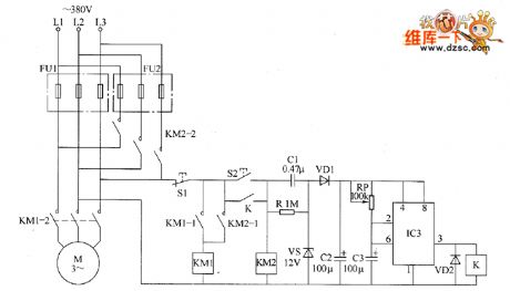
The motor dual insurance starter circuit is composed of the Road 1 fuse FU1, Road 2 fuse FU2, stop button R1, start button S2, AC contactors KM1, KM2, relay K, capacitors C1 ~ C3, diodes VD1, VD2, resistor R, voltage regulator diode VS, potentiometer RP and time-based integrated circuit IC, the circuit is shown as the chart. After people press the start button S2, KM2 pulls in and its normally open contacts KM2-i and KM2 ˉ 2 are connected, the motor M operates. At the same time, the AC voltage across L2, L3 is bucked by C1, stabilized by VS, filtered by VD1 and rectified by C2 to provide the +12 V power supply for IC. R uses 1W metal film resistor. RP selects small organic solid potentiometer or variable resistor. IC uses NE555 base integrated circuit.
(View)
View full Circuit Diagram | Comments | Reading(4292)
Motor decompression starter circuit diagram 2
Published:2011/5/21 23:32:00 Author:Lucas | Keyword: Motor decompression starter
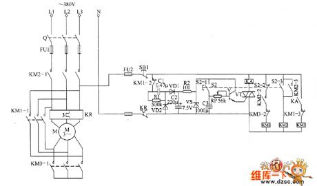
Motor decompression starter is composed of the power supply circuit, the delay control circuit and control implementation circuit, the circuit is shown as the chart. Power supply circuit is composed of the fuses FU1, FU2, stop button S1, capacitors C1, C2, the normally closed contacts of thermal relay KR , resistors R1, R2 and Zener diode VS. Delay control circuit is composed of the start control button S2 (S2-1 ~ S2-3), capacitor C3, potentiometer RP, transistors V, VT and intermediate relay KA. Control implementation circuit is composed of AC contactors KM1 ~ KM3, linkage contacts S2-2, S2-3 of qo and the normally open contacts of KA. AC 220V voltage is bucked by C1, rectified by VD1, filtered by C2, limited by R2 and stabilized by VS to produce the 7.5V DC voltage, which is added to the collector of V. R1 and R2 select 1/4W metal film resistors. RP uses synthetic carbon potentiometer.
(View)
View full Circuit Diagram | Comments | Reading(755)
Motor decompression starter circuit diagram 1
Published:2011/5/21 23:21:00 Author:Lucas | Keyword: Motor decompression starter

Motor decompression starter is composed of decompression starting control circuit and protection circuit. the circuit is shown as the chart. Decompression starting control circuit is composed of the start button S1, the master controller (Q2a, Q2b), AC contactors KM1 ~ KM3, intermediate relays KA1, KA2, time relay KT, auto transformer TA1 and so on. Protection circuit consists of the power transformer T, the diodes VD1 ~ VD5, capacitors C1 ~ C3, three-terminal integrated voltage regulator integrated circuit IC1, potentiometer RP, time-base integrated circuit IC2 and relay Κ and so on. TA2, TA3 are the current transformers, KR1 and KR2 are the thermal relays, QS is the circuit breaker. C1 and C2 select the luminum electrolytic capacitors with voltage in 25V a; C3 and CZ choose monolithic capacitors. RP uses small potentiometer or variable resistor. VD1 ~ VD5 select 1N40071N rectifier diodes.
(View)
View full Circuit Diagram | Comments | Reading(2293)
Motor protector circuit diagram 18
Published:2011/5/20 20:35:00 Author:Lucas | Keyword: Motor protector

The motor protection circuit is composed of the power circuit, phase sequence detection circuit, monostable circuit and control implementation circuit, the circuit is shown as the chart. Power circuit is composed of the power transformer T, rectifier diodes VD1, VD2, capacitors C1, C2, and three-terminal voltage regulator integrated circuit IC1. Phase sequence detection circuit is composed of the diodes VD3 ~ VD5, resistors R1 ~ RIO, capacitor C6, four NAND gate Schmitt trigger integrated circuit IC2 (D1 ~ D4) and dual JK master-slave flip-flop integrated circuit IC3. Monostable circuit is composed of the resistors R11 ~ R13, capacitors C3 ~ C5 and time-based integrated circuit IC4. Control implementation circuit is composed of the resistor R14, transistor V, diode VD6 and relay K and other components. Knife switch Q, fuse FU, AC contactor KM and KR form the origin control circuit of motor M .
(View)
View full Circuit Diagram | Comments | Reading(2965)
Motor protector circuit diagram 16
Published:2011/5/20 21:04:00 Author:Lucas | Keyword: Motor protector

The motor protector circuit is composed of the AC contactors KM1 ~ KM3, knife switches Q1, Q2 and motor M, the circuit is shown as the chart. When 380V AC supply voltage is normal, the AC contactors KM1 ~ KM3 get power and pull in, their 3 groups of normally open contacts are connected, then closing the knife switch Q2 will make motor M get power and operate. When the AC 380V voltage is open-phase because of thunder or other reasons, one contactor of KM1 ~ KM3 couldn't pull in or get power, the power supply circuit of motor M will cut off to protect the motor M. For example, the voltage on L2 phase line disappears, AC contactor KM2 releases, the normally open contacts KM2-1 ~ KM2-3 cut off. KM1 ~ KM3 select the 220V AC voltage contactor.
(View)
View full Circuit Diagram | Comments | Reading(777)
Motor protector circuit diagram 15
Published:2011/5/20 22:03:00 Author:Lucas | Keyword: Motor protector

The motor protector circuit detection circuit is composed of the current sampling circuit and light control protection circuit, the circuit is shown as the chart. Current sampling detection circuit consists of sampling resistors R1 ~ R3. Light control protection circuit is composed of the protection diodes VD1 ~ VD12, small bulbs HL1 ~ HL3, photosensitive resistors RC1 ~ RC3 and thyristors VT1 ~ VT3. Q is the fuse knife switch, FU is fuse, S1 is stop button, S2 is the start button, KM is the AC contactor. R1 ~ R3 select 5 ~ 1OW wire wound resistors, the resistance should be based on the rated power of motor. If it uses 1.5kW motor, the rated current is about 3A, the sampling resistors can be set at 0.3Ω. RG1 ~ RG3 use MC45 series of light-sensitive resistors. VD1 ~ VD12 use 1N5408 silicon rectifier diodes. VT1 ~ VT3 select MAC97A6 bidirectional thyristors.
(View)
View full Circuit Diagram | Comments | Reading(663)
Motor electronic speed controller circuit diagram 3
Published:2011/5/20 20:06:00 Author:Lucas | Keyword: Motor , electronic speed controller

The motor electronic speed controller circuit consists of power supply circuit, counter and the light control pulse width modulation circuit, the circuit is shown as the chart. Power supply circuit is composed of the switch S1, step-down capacitor C1, resistor R1, rectifier diodes VD1 and VD2, Zener diode VS and filter capacitors C2, C3. IC2 is the decimal counter IC, its pin 14 (CLK-side) is the count pulse signal input and connceted the resistors R3 and button S2. When people press S2 each time, pin 14 of IC2 will input a count pulse, when people press S2 continuously, the Y1 ~ Y6 output end of IC2 will output high level in the turn. The resistors R4 ~ R9 are gradually increasing, when the different output ends output high level, the current flowing the LED is different to make the brightness of VL1 being gradually weaking from strong.
(View)
View full Circuit Diagram | Comments | Reading(1174)
Warping machine automatic controlled economizer circuit diagram
Published:2011/5/21 23:51:00 Author:Lucas | Keyword: Warping machine , automatic controlled, economizer
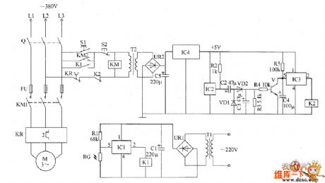
The warping machine automatic controlled economizerircuit consists of the light control circuit, magnetic circuit, +5 V power supply circuit and motor main control circuit, the circuit is shown as the chart. Light control circuit consists of photoresistor RC, resistor R1, electronic switch integrated circuit IC1, relay K1, filter capacitor Cl, bridge rectifier UR1 and power transformer T1. Magnetic circuit is composed of the Hall sensor integrated circuit IC2, resistors R2 ~ R5, electronic switch integrated circuit IC3, capacitors C2 ~ C4, diodes VD1, VD2, transistor V and relays K2. +5 V power supply circuit is composed of the power transformer T2, bridge rectifier UR2, filter capacitor C5 and three-terminal voltage regulator integrated circuit IC4. The motor main control circuit consists of knife switch Q, start button S1, stop button S2, fuse FU, AC contactor KM and thermal relay KR.
(View)
View full Circuit Diagram | Comments | Reading(1487)
Optical proximity switch circuit diagram
Published:2011/5/22 0:06:00 Author:Lucas | Keyword: Optical, proximity switch
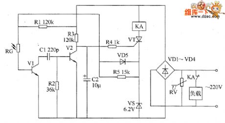
The optical proximity switch circuit consists of the photosensitive resistor RG, varistor RV, transistors V1 and V2, resistors R1 ~ R5, capacitors C1 and C2, voltage regulator diode VS, thyristor VT and diodes VD1 ~ VD5 etc. the circuit is shown as the chart. RV is the pressure sensitive resistor for protection to prevent the surge voltage shocks. During the turn-in VT, the 6V voltage on the VS can provide working power for the optical circuit by R7. R1 ~ R5 select 1/4W metal film resistors. RC uses the photosensitive resistor with light resistance being less than 20kΩ, the dark resistance being greater than 500kΩ . RV uses 270V varistor. C1 uses high-frequency ceramic capacitor or mica capacitor; C2 uses the aluminium electrolytic capacitor with the voltage in 16V. VD1 ~ VD5 use 1N4007 silicon rectifier diodes. VS selects 1N4735 (1W, 6.2V) silicon voltage regulator diode. V1 and V2 use 59013 silicon NPN transistor. VT uses MCR100-6 intergranular tube. KA uses intermediate relay with the coil voltage in DC 220V, and the current capacity on its contact should be based on rational power of load.
(View)
View full Circuit Diagram | Comments | Reading(1607)
Motor protector circuit diagram 8
Published:2011/5/21 1:44:00 Author:Lucas | Keyword: Motor protector

The motor protection circuit is composed of power supply circuit, current detection circuit and protection control circuit, the circuit is shown as the chart. Power circuit is composed of the power transformer T, rectifier diode VD4, filter capacitors C4, C5, current limiting resistor R8 and Zener diode VS and other components, the circuit is used to generate +20 V voltage for relay K and its drive circuit. Current detection circuit is composed of the current transformers LA1, LA2, LA3, and rectifier diodes VD1 ~ VD3, filter capacitors C1 ~ C3 and other components. The protection control circuit is composed of resistors R1 ~ R7, transistors V1 ~ V3, relay Κ, AC contactors KMI and KM2 and start button S1, stop button S2. After people press the start button S1, AC power contactor KM1 works, the three contacts are connected, the motor M operates.
(View)
View full Circuit Diagram | Comments | Reading(1764)
Motor protector circuit diagram 7
Published:2011/5/21 1:26:00 Author:Lucas | Keyword: Motor protector

When the three-phase power supply is normal, the public contact 0 of detection capacitor C1 ≈ C3 has no current flowing, the two ends of C4 have no voltage, and the crystal tube VT is off, the relay K does not pull in, its normally closed contact is connected, the LED VL does not emit light, the motor M operates normally (in fact, the three-phase voltage unbalance, or the capacity of C1 ~ C3 differ will cause O point having a small current to flow, but the K doesn't move.) KR is the thermal relay, S1 is the Close button, S2 is the start button, R is the current limiting resistor. Potentiometer RP, capacitor C5 or intergranular tube VT form delay circuit to prevent serious harmonic interference or instantaneous voltage fluctuations and protector's malfunction. RP's positive adjustment value can change the conduction delay time of VT (generally 0.5 ~ 1s).
(View)
View full Circuit Diagram | Comments | Reading(562)
Electronic QN circuit diagram 4
Published:2011/5/26 4:25:00 Author:Lucas | Keyword: Electronic QN

The electronic QN circuit is composed of the rectangular wave generator, electronic switching circuit, self-excited multivibrator and audio driver amplifier circuit, the circuit is shown as the chart. Rectangular wave generator circuit consists of operational amplifier integrated circuit IC, resistors R1 ~ R4, potentiometer RP1, diodes VD1, VD2, voltage regulator diode sVS1, VS2 and capacitor C2. Electronic switch circuit is composed of the field-effect transistor VF1, resistor R5 and VS1, VS2. Self-excited multivibrator by the transistors V1, V2, resistors R6 ~ R9 and capacitors C3, C4 composition. Audio driver amplifier consists of potentiometer RP2, voltage regulator diode VS3, resistor R1O, field-effect transistor VF2 and speaker BL.
(View)
View full Circuit Diagram | Comments | Reading(590)
The electronic QN circuit diagram 2
Published:2011/5/26 4:36:00 Author:Lucas | Keyword: electronic QN

The electronic QN circuit is composed of the multi-vibrator circuit, step-up circuit, voltage regulator, low frequency oscillator and the magnet control circuit and other components, the circuit is shown as the chart. Multivibrator is composed of six NOT gate integrated circuit IC (D1 ~ D6) and D1, D2 and capacitor C1, resistor R1 which is inside of NOT gate circuit. Step-up circuit consists of the transistor V1, step-up transformer T, rectifier diode VD1, resistors R2, R3 and capacitors C2, C3 and so on. Regulator circuit consists of resistors R4 ~ R6 and zener diodes VS. Low-frequency oscillator circuit is composed of the D3 ~ D6 and resistor R7, capacitor C4, diode VD2 which is inside of NOT gate. Solenoid control circuit is composed of the transistor V2, the relay K, diode VD3 and solenoid YV.
(View)
View full Circuit Diagram | Comments | Reading(752)
Electronic QN circuit diagram 1
Published:2011/5/26 4:29:00 Author:Lucas | Keyword: Electronic QN

The electronic QN circuit is composed of the clock pulse generator, counter / pulse distributor, sound generator circuit, audio amplifier and power supply circuis and other components, the circuit is shown as the chart. Clock pulse generator circuit consists of time-base integrated circuit IC1 and self-excited multivibrator composed of the external RC components. Counter / pulse divider circuit consists of integrated circuit IC2 and resistor R3, capacitor C3. Sound generator circuit consists of Audio integrated circuits IC3 ~ IC5 and external RC components. Audio amplifier circuit consists of the power amplifier IC IC6, speaker BL, diodes VD1, VD2 and external RC components. Power circuit is composed of the power switch S, the power transformer T, rectifier bridge pile UR, filter capacitors C13, C14, C9, current limiting resistor R8 and Zener diode VS and so on.
(View)
View full Circuit Diagram | Comments | Reading(947)
Agricultural automatic water supply device circuit diagram 5
Published:2011/5/21 11:18:00 Author:Lucas | Keyword: Agricultural , automatic , water supply device

The agricultural automatic water supply device circuit is composed of supply circuit, water level measuring control circuit, water protection outage circuit and pump motor starter operation circuit, the circuit is shown in Figure 1. Power circuit is composed of fuse FU1, power transformer T, rectifier diodes VD4 ~ VD7, filter capacitors C4, C5, and three-terminal voltage regulator integrated circuit IC. Water level measuring control circuit consists of water level detection electrodes a ~ c, resistors R1, R2, capacitors C1, C2, transistors V1 ~ V4, diodes VD1, VD2 and relays K1, k2. Water protection outage circuit is composed of the detection electrodes A, B, resistor R3, capacitor C3, transistor V5, composed of diodes VD3 and relay K3. Pump motor starter operation circuit is composed of knife switch Q, fuse FU2, control buttons S1, S2, AC contactor KM1 ~ KM3, time relay KT and pump motor M. AC 220V voltage is bucked by T, rectified by VD4 ~ VD7 , filtered by C5 and stabilized by IC to provide +12 V voltage for the water level measuring control circuit and water protection outage circuit.
(View)
View full Circuit Diagram | Comments | Reading(1933)
| Pages:1837/2234 At 2018211822182318241825182618271828182918301831183218331834183518361837183818391840Under 20 |
Circuit Categories
power supply circuit
Amplifier Circuit
Basic Circuit
LED and Light Circuit
Sensor Circuit
Signal Processing
Electrical Equipment Circuit
Control Circuit
Remote Control Circuit
A/D-D/A Converter Circuit
Audio Circuit
Measuring and Test Circuit
Communication Circuit
Computer-Related Circuit
555 Circuit
Automotive Circuit
Repairing Circuit