
Circuit Diagram
Index 1838
555 electronic health care toothbrush circuit
Published:2011/5/24 2:54:00 Author:TaoXi | Keyword: electronic, health care, toothbrush circuit
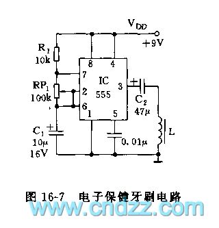
As the figure 16-7 shows, the health care toothbrush circuit uses the 555 to form a low frequency oscillator, f=1.44/(R1+RP1)C1.
The figure parameter's oscillation frequency is 1-20Hz, you can select the appropriate frequency of oscillation by adjusting RP1, the output drives an electromagnetic armature through the capacitor C2, and this circuit changes the output voltage into the small amplitude of mechanical vibration, and it drives the brush head to vibrate, clean, and massage the gum to promote the blood circulation and keep health.
(View)
View full Circuit Diagram | Comments | Reading(1302)
555 fall down SOS device circuit
Published:2011/5/24 2:54:00 Author:TaoXi | Keyword: fall down, SOS
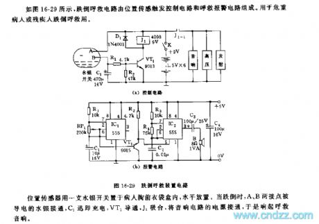
As the figure 16-29 shows, the fall down SOS device is composed of the position sensing trigger control circuit and the SOS alarm circuit. It can be used to help the critically ill patients or the disabled person.
The position sensor is in the patient's chest pocket, and it is horizontal. When the patient falls down, the contact points A and B are connected by the conductive mercury, C1 charges, VT1 conducts, J1 closes, and the speaker circuit power is connected.
The astable multivibrator is composed of the IC1 and R1,RP1,C1, the oscillation period T=1 second.
(View)
View full Circuit Diagram | Comments | Reading(730)
555 multifunction electronic acupoint detection and therapeutic equipment circuit
Published:2011/5/24 1:00:00 Author:TaoXi | Keyword: multifunction, electronic, acupoint detection, therapeutic equipment
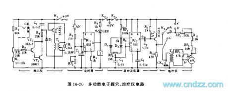
As the figure 16-20 shows, this multifunction electronic acupoint detection and therapeutic equipment circuit is composed of the acupoint detection circuit, the timer, the pulse generator and the amplifier output stage, it can be used in the acupoint detection and the no needle electrotherapy applications.
The acupoint detector is composed of the VT1,VT2,R1~R4,RP1,C1,VT3 and T1.etc, actually it is a audio oscillator. The timing circuit is composed of the IC1(555), R4,RP2 and C3. The astable multivibrator is composed of the IC2 and RP4,R8,D3,D4,RP3, C4, the oscillation frequency f=1.44/(RP4+RP3+R8)C4, the oscillation frequency and the duty ratio are adjustable.
(View)
View full Circuit Diagram | Comments | Reading(1014)
555 DGK—63L double functions disinfection cabinet circuit
Published:2011/5/25 4:06:00 Author:TaoXi | Keyword: 555, double functions, disinfection cabinet
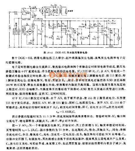
The DGK—63L double functions disinfection cabinet circuit is composed of three parts: the infrared ray high temperature generating circuit, the ozone generating circuit and the electronic timing control circuit.
The electronic timing control circuit is composed of the AC step-down circuit, the rectifier voltage stabilization circuit and two monostable timing control circuits. The voltage stabilization circuit outputs the +9V DC voltage as the power supply of the control circuit. The button type monostable trigger timing circuit is composed of the IC1(555), R3,C4 and AN1, if you press AN1, the IC1's trigger setting port pin-2 connects to the ground electric potential to make the 555 to set, so pin-3 has the high electric potential, relay K1 closes, it's connection point K1-1 closes too.
(View)
View full Circuit Diagram | Comments | Reading(615)
Motor protector circuit diagram 10
Published:2011/5/21 10:38:00 Author:Lucas | Keyword: Motor protector

The motor protector circuit is composed of voltage detection circuit and protection control implementation circuit, the circuit is shown as the chart. Starting control circuit is composed of stop button S1, start button S2, AC contactor KM ( the original motor starting circuit). Voltage detection circuit is composed of the diodes VD1 ~ VD3, voltage regulator diodes VS1 ~ VS3, resistors R1 ~ R6, capacitors C1 ~ C3 and optocouplers VLC1 ~ VLC3. Protection control circuit consists of transistors V, relay K, diode VD4 and resistor R7. If one phase of the three-phase AC power is open-phase, the optocoupler in voltage detection circuit is turning off, V could not turn on, K does not pull in, disconnecting S2 will make KM released immediately to achieve fault phase automatic protection purpose. R1, R3 and R5 use 1 ~ 2W metal film resistors.
(View)
View full Circuit Diagram | Comments | Reading(1236)
Motor protector circuit diagram 11
Published:2011/5/21 10:28:00 Author:Lucas | Keyword: motor protector

The motor protector circuit consists of capacitors C1 ~ C5, diodes VD1 ~ VD5, resistors R1, R2, zener diode VS, light-emitting diode VL, single-junction transistor VU and relay K, the circuit is shown as the chart. When the three-phase supply of L1 ~ L3 is in the normal, the junction point A on capacitors C1 ~ C3 has the lower AC voltage, the voltage is rectified by the VD1 ~ VD4, filtered by C4, so it is insufficient to turn on VS and VU, k does not pull in, the motor M operates normally. When the three-phase power is restored to normal, after a short delay VU deadline, K releases, then people can press the start button to restart the motor S2. R1 and R2 use 1/4W carbon film resistors or metal film resistors. C1 ~ C3 select CBB capacitors with the voltage being more than 400V: C4 and C5 select electrolytic capacitors, the withstand voltage of C4 is 25V, the withstand voltage of C5 is 16V. VD1 ~ VD5 use 1N4007 silicon rectifier diodes.
(View)
View full Circuit Diagram | Comments | Reading(618)
Motor protector circuit diagram 12
Published:2011/5/21 1:47:00 Author:Lucas | Keyword: Motor protector

The motor protector circuit is composed of the power supply circuit and voltage detection control circuit, the circuit is shown as the chart. Power circuit is composed of the power transformer T, rectifier diode VD3 and filter capacitor C3. Voltage detection control circuit is composed of the potentiometer RP, diodes VD1, YD2, capacitors C1, C2, voltage regulator diode vs, resistor R, transistors V1, V2 and relays K. KM is the the original AC contactor in the motor control circuit, S1 and S2 are the stop button and start button respectively in the original motor control circuit of motor. AC 220V voltage is bucked by T, half-wave rectified by VD3 and filtered by C3 to provide DC operating power for K and its driving circuit.
(View)
View full Circuit Diagram | Comments | Reading(673)
Time relay circuit diagram 1
Published:2011/5/20 23:51:00 Author:Lucas | Keyword: Time relay
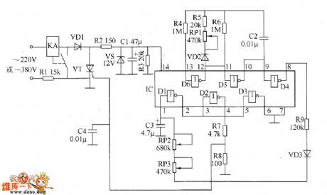
The relay circuit is composed of +12 V power supply circuit, oscillator circuit, delay trigger circuit and electronic switching circuit, the circuit is shown as the chart. +12 V power supply circuit consists of resistors R1 ~ R3, intermediate relay KA coil, diode VD1, Zener diode VS and filter capacitor C1. Oscillation circuit is composed of NOT gate IC (D1 ~ D6) within the NOT gates D5, D6, and capacitor C2, resistors R4 ~ R6, potentiometer RP1, diode VD2. Delay trigger circuit is composed of the IC within the NOT gates Dl, D2, D4, resistors R9, potentiometers RP2, RP3, capacitor C3 and diode VD3. Electronic switching circuit consists of intermediate relay KA, intergranular tube VT, resistors R7, R8 and capacitor C4.
(View)
View full Circuit Diagram | Comments | Reading(903)
Time relay circuit diagram 2
Published:2011/5/21 0:07:00 Author:Lucas | Keyword: Time relay
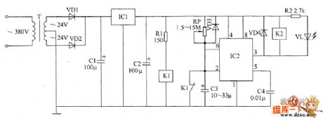
The relay circuit is composed of the power supply circuit, monostable circuit and relay control circuit, the circuit is shown as the chart. Power circuit is composed of the power transformer T, rectifier diodes VD1, VD2, three-terminal voltage regulator integrated circuit IC1 and filter capacitors C1, C2. Monostable circuit is composed of the potentiometer RP, diode VD3, capacitors C3, C4, time-base integrated circuit IC2 and the normally closed contact of relay K1. Relay control circuit consists of resistors R1, R2, relays K1, K2, diode VD4 and light emitting diode VL. R1 uses 1/2W metal film resistor; R2 uses 1/4W metal film resistor. RP uses organic, solid variable resistor. C1 uses aluminium electrolytic capacitor with the voltage in 50 V; C2 and C3 select aluminium electrolytic capacitor with the voltage in 13 V; C4 uses monolithic capacitor or polyester capacitor.
(View)
View full Circuit Diagram | Comments | Reading(843)
Time relay circuit diagram 3
Published:2011/5/21 0:24:00 Author:Lucas | Keyword: Time relay
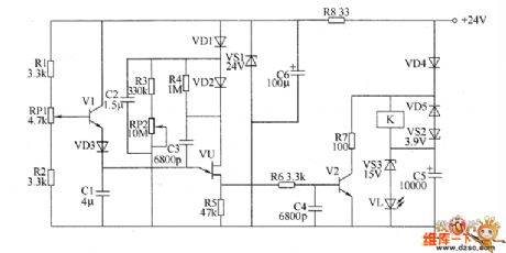
The relay circuit is composed of the regulator filter circuit, delay charging and discharging circuit and relay control circuit, the circuit is shown as the chart. Regulating filter circuit consists of resistor R8, zener diode VS and filter capacitor C6. Delay charging and discharging circuit consists of resistors R1 ~ R5, capacitors RP1 and RP2, transistor V1, capacitors Cl ~ C3, diodes VD1 ~ VD3 and single-junction transistor VU. Relay control circuit consists of resistors R6 and R7, capacitors C4 and C5, diodes VD4 and VD5, voltage regulator diodes VS2 and VS3, transistor V2, light-emitting diode VL and relay K. R1 ~ R6 select 1/4W metal film resistors; R7 uses 2W wirewound resistor; R8 selects 1/2W metal film resistor. RP1 uses multi-turn wirewound potentiometer; RP2 uses organic, solid potentiometer.
(View)
View full Circuit Diagram | Comments | Reading(766)
Portable SCR charger circuit
Published:2011/5/24 2:43:00 Author:John | Keyword: Portable SCR charger

Charger directly uses 220V AC power supply. It achieves the output voltage adjustment starting from 0V by controlling the triggering circuit. It is suitable for charging 12V-220V battery (s).
The main control circuit is composed by the fuse FU, ammeter and SCR VS. When the battery, as well as the batteries, requiring being charged is connected, the SCR VS gains trigger pulse. Conduction angle of VS is regulated by pulses with different width. And the RP can be adjusted to meet the charge of different battery or batteries within different charging current or voltage. (View)
View full Circuit Diagram | Comments | Reading(4927)
Maintenance-free sealed micro-battery circuit
Published:2011/5/24 3:02:00 Author:John | Keyword: micro-battery

Micro-battery described in this article has the following characteristics: (1) There is no liquid flow inside, so that it can be placed in any direction without influencing the function. (2) There is no need for acid-supply and other maintenance work during the entire applying process. The battery surface is clean and not damp. (3) Gases produced by the charging process can be absorbed by a special anode. The overall sealed performance can be achieved. So it is not necessary to worry about the corrosion and pollution to electrical equipment.(4) Its charge and discharge cycles can be over more than 300 times within proper use. And the service life is up to 3 years. (5) It has very low ability to internal self-discharge. Its rate for self-discharging is less than 1%. (View)
View full Circuit Diagram | Comments | Reading(1146)
active load circuit
Published:2011/5/24 5:15:00 Author:John

Q1 and Q2 constitute a Schmitt trigger. Constant current LED NSL4944 is regarded as load collector, providing output of 12V and 40mA. When the bulb is not conducting with Q2, most current of the light-emitting diode flows through the resistor with resistance of 100Ω. So the voltage in trigger circuit is limited to 2V. When the control signal saturates Q1, Q2 supplies the lamp with voltage of about 1V. Such plays a role of preheating and reducing voltage for starting. Q2 is conducted to light the bulb.
(View)
View full Circuit Diagram | Comments | Reading(983)
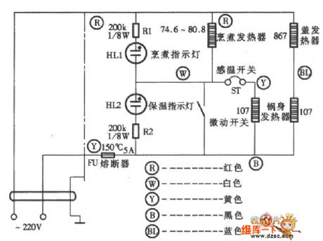
Rong Sheng CFXB50-90DA multi-purpose rice cooker circuit
Published:2011/5/24 0:10:00 Author:John | Keyword: multi-purpose rice cooker
Rong Sheng CFXB50-90DA multi-purpose rice cooker circuit is shown below.
(View)
View full Circuit Diagram | Comments | Reading(1482)
touch switch delay circuit
Published:2011/5/24 0:13:00 Author:John | Keyword: touch switch


Touch switch delay circuit is shown below.
(View)
View full Circuit Diagram | Comments | Reading(1833)
light control switch circuit with photosensitive resistor (LDR)
Published:2011/5/24 0:28:00 Author:John | Keyword: light control switch, photosensitive resistor

Where there is light, the transistor with photoresistor LDR in the circuit is connected in high power level or in zero level. The amplification factor of transistor β is sufficient if it is >100. And the resistance of photosensitive resistor would be between the 100Ω ~ 100KΩ. Such is arranged to be respectively corresponding to light irradiation situations and dark conditions. If it is expected to control a higher power load, it should use Darlington transistors.
(View)
View full Circuit Diagram | Comments | Reading(1822)
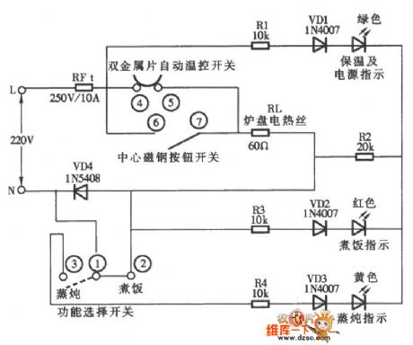
CFXB50-2P electronic thermal-type rice cooker circuit
Published:2011/5/24 0:30:00 Author:John | Keyword: thermal-type rice cooker
CFXB50-2P electronic thermal-type rice cooker circuit is shown below.
(View)
View full Circuit Diagram | Comments | Reading(918)
crystal diode DDZX6V8CTS internal circuit
Published:2011/5/24 1:03:00 Author:John | Keyword: crystal diode

Crystal diode DDZX6V8CTS internal circuit is shown below.
(View)
View full Circuit Diagram | Comments | Reading(532)
Rechargeable battery technology and charging method circuit
Published:2011/5/24 1:48:00 Author:John | Keyword: Rechargeable battery

Battery applications have never been so extensive. Batteries are becoming smaller and lighter. And they can accommodate more energy in every unit volume. The main driving force of the battery is mainly from the development of portable devices (mobile phones, laptop computers, camcorders, MP3 players).
This article outlines the battery charging methods and modern technology, in order to make people better understand the batteries used in portable devices. These include battery chemistry description for nickel-cadmium (NiCd), nickel metal hydride (NiMH) and lithium-ion (Li +). This article also describes protection devices for single-cell lithium ion and lithium-ion polymer battery. (View)
View full Circuit Diagram | Comments | Reading(1192)
DC photoelectric switch circuit
Published:2011/5/24 2:05:00 Author:John | Keyword: DC photoelectric switch

Phototransistor BPX25 in Figure (a) stops where there is no light irradiation. So the no base current of transistor BC141 is off. Otherwise, the transistor opens to trigger thyristor to conduct. Then, voltage is on the negative cut-off side.
The Figure (B) shows the opposite situation. When light shines into the phototransistor, the transistor BC141 conducts to cut-off the thyristor. Then the load-power cuts off. When there is no light, the transistor BC141 deadlines. So the DC voltage is added to the poles of thyristor through the resistors with resistance of 470Ω and 47Ω. Then the thyristor conducts to connect load circuit.
(View)
View full Circuit Diagram | Comments | Reading(1832)
| Pages:1838/2234 At 2018211822182318241825182618271828182918301831183218331834183518361837183818391840Under 20 |
Circuit Categories
power supply circuit
Amplifier Circuit
Basic Circuit
LED and Light Circuit
Sensor Circuit
Signal Processing
Electrical Equipment Circuit
Control Circuit
Remote Control Circuit
A/D-D/A Converter Circuit
Audio Circuit
Measuring and Test Circuit
Communication Circuit
Computer-Related Circuit
555 Circuit
Automotive Circuit
Repairing Circuit