
Circuit Diagram
Index 1823
Character display type logic pen circuit (CD4069) composed of the gate circuit (1)
Published:2011/5/26 7:31:00 Author:Christina | Keyword: Character display, logic pen, gate circuit
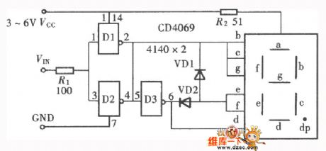
The character display type logic pen is as shown, here the characters are not our chinese characters 高 and 低 , they are the english characters H and L . For the particularity of the two characters' glyph, and this particularity is the same as the LED digital tube's pen section, so we are easy to use it to form the logic level test pen.
(View)
View full Circuit Diagram | Comments | Reading(782)
Single phase electromotor thyristor stepless speed regulation circuit
Published:2011/5/26 8:43:00 Author:Christina | Keyword: Single phase, electromotor, thyristor, stepless, speed regulation

As the figure shows, the adjusting potentiometer RP can adjust the conduction angle of the thyristor to change the output voltage, so it achieves the purpose of the electromotor revolving speed stepless adjusting. If the RP resistance value is small, the VS conduction angle is big, the output voltage is high, so the electromotor revolving speed is high; on the contrary, if the RP resistance value is big, the electromotor revolving speed is low.
(View)
View full Circuit Diagram | Comments | Reading(807)
AC/DC darkroom safelight circuit
Published:2011/5/26 21:13:00 Author:Christina | Keyword: AC, DC, darkroom, safelight
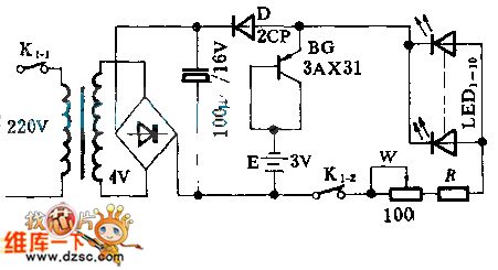
This circuit has the function of non-contactor auto-convert switch, and it uses the orange color LED.
When the power supply is normal, the rectifying power supply supplies power to the LED; when the power is failure, the battery E supplies power to LED through BG. Once the city electricity recovers, BG automaticly cuts off.
(View)
View full Circuit Diagram | Comments | Reading(986)
TOSHIBA F3SS color TV movement protection circuit
Published:2011/5/26 21:02:00 Author:Christina | Keyword: TOSHIBA, color TV, movement, protection circuit
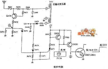
1.+B line over-current protection circuit
When the +B line is over-current, the current of R470 increases, the pressure drop of R470 increases. When the pressure drop of R470 makes the e electrode's voltage higher than b electrode (0.7V), the Q470 conducts.
2.+B over-voltage protection circuit
When the +B line is over-voltage, the pulse voltage which is output by the line output transformer is rectified by D408, then is filtered by C449.
3.Field output over-current protection circuit
When the output current is over-current, the pin-6's voltage of the supply field output integrated circuit Q301 reduces, the pressure drop of resistance R490 increases, the Q490 conducts, the D490 conducts, the D471 conducts, the Q838 conducts. (View)
View full Circuit Diagram | Comments | Reading(840)
Winding rotor electric motor reverse connection braking circuit
Published:2011/5/29 22:41:00 Author:Christina | Keyword: Winding, rotor, electric motor, reverse connection, braking circuit

The Winding rotor electric motor reverse connection braking circuit is as shown:
(View)
View full Circuit Diagram | Comments | Reading(2236)
Anti-theft alarm telephone system circuit
Published:2011/6/1 20:50:00 Author:Christina | Keyword: Anti-theft, alarm telephone, system circuit
Anti-theft alarm telephone system circuit (View)
View full Circuit Diagram | Comments | Reading(475)
historical relic anti-thief alarm circuit
Published:2011/6/1 20:21:00 Author:Christina | Keyword: historical relic, anti-thief, alarm circuit
historical relic anti-thief alarm circuit (View)
View full Circuit Diagram | Comments | Reading(417)
Baby sleep state monitor circuit
Published:2011/6/1 20:17:00 Author:Christina | Keyword: Baby, sleep state, monitor
The Baby sleep state monitor circuit (View)
View full Circuit Diagram | Comments | Reading(508)
Heat release electricity infrared detector alarm circuit
Published:2011/6/1 20:18:00 Author:Christina | Keyword: Heat release, electricity, infrared detector, alarm circuit
Heat release electricity infrared detector alarm circuit (View)
View full Circuit Diagram | Comments | Reading(423)
Heat release electricity infrared control electronic dog circuit
Published:2011/6/1 20:19:00 Author:Christina | Keyword: Heat release, electricity, infrared control, electronic dog
Heat release electricity infrared control electronic dog circuit (View)
View full Circuit Diagram | Comments | Reading(403)
human body control electric fan circuit
Published:2011/6/1 20:20:00 Author:Christina | Keyword: human body, control, electric fan
human body control electric fan circuit (View)
View full Circuit Diagram | Comments | Reading(516)
The circuit diagram of preamplifier made by MC1709 serves the electric motor drive
Published:2011/6/1 22:33:00 Author:leo | Keyword: The circuit diagram of preamplifier made by MC1709 serves the electric motor drive, MC1709

What Picture 1 shows is a kind of preamplifier made by MC1709 serves the electric motor drive circuit. In this circuit, the voltage plus of symbolic amplifier circuit is 39 dB. The circuit is made up of MC1709 and so on. The bandwidth of amplifier is 41 KHz which is decided by R5 and C2.Its single-ended output passes through the phase position of VT2 and is divided into two signals with discrepancy of 180 degree angle. This process will drive sh-pull (PP) output amplifier.
(View)
View full Circuit Diagram | Comments | Reading(1798)
The circuit diagram of preamplifier made by MC1437 serves the electric motor drive
Published:2011/6/1 22:36:00 Author:leo | Keyword: The circuit diagram of preamplifier made by MC1437 serves the electric motor drive, MC1437

What Picture 1 shows is a kind of preamplifier made by MC1437 serves the electric motor drive circuit. In this circuit, the voltage plus of symbolic amplifier circuit is 39 dB. The circuit is made up of MC1709 and so on. The bandwidth of amplifier is 41KHz which is decided by R5 and C2.Its single-ended output passes through the phase position of VT2 and is divided into two signals with discrepancy of 180 degree angle. This process will drive sh-pull (PP) output amplifier. (View)
View full Circuit Diagram | Comments | Reading(813)
MC68HCO5C4P-Communication single-chip microcomputer integrated circuit diagram
Published:2011/6/1 22:24:00 Author:leo | Keyword: MC68HCO5C4P-Communication single-chip microcomputer integrated circuit diagram
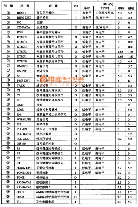
MC68HCO5C4P is a kind of communication single-chip microcomputer integrated circuit made by Motorola which can be applied in wireless telephone and is used as host control chip in cell phone.
1.Function Feature:The integrated circuit MC68HCO5C4P has one more 'P' than MC68HCO5C4. But they have part of different pins and cannot change directly for the same usage.MC68HCO5C4P is improved on the base of MC68HCO5C4. So most of functions of them are similar which can be found in the introduction of MC68HCO5C4 functions.
2.Pin Functions and dataThe integrated circuit MC68HCO5C4P adopts 40-pin package and is used together with MC68HC5PI. All pins function and data of the integrated circuit are shown in the picture bellow. (View)
View full Circuit Diagram | Comments | Reading(648)
Biploar Current Sources Circuit Diagram of Optical Coupler
Published:2011/5/20 20:12:00 Author:leo | Keyword: Biploar Current Sources Circuit Diagram of Optical Coupler, PS2501
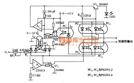
In the picture, there is a bipolar current sources circuit of optical coupler which consists of two operational amplifiers and four optical couplers. It is used to control the floating bridge output port using the battery for power supply, which is made up of PC3 to PC6.Its feature is to get the bipolar output current sources from single battery UB and adopt single-channel optical coupler PC1 as the control circuit of current output. At the same time, it is also used to improve the output polarity when output current is symmetric. (View)
View full Circuit Diagram | Comments | Reading(933)
Motor protector circuit diagarm 5
Published:2011/6/1 20:02:00 Author:Lucas | Keyword: Motor protector

The motor protector circuit is composed of the ring current transformer TA, protection relay KP, start button S1, stop button S2, inching button S3, AC contactor KM and thermal relay KR and other components, and the circuit is shown as the FU1. Turning on the start button S1 will make KM get power and lock-hold, and the motor M will get power and operate; if pressing the inching button KR53 will make the M get power and operate. M will be turned off after A3 being reset. When one phase of the three-phase AC power supply open occurs phase, AC power contactor KM will be released, and the motor M stops to protect the motor and prevent their damage from phase running. When the motor M is over-current or overload, thermal relay KR operates to make the KM release and M stop.
(View)
View full Circuit Diagram | Comments | Reading(2063)
Motor protector circuit diagarm 4
Published:2011/6/1 20:07:00 Author:Lucas | Keyword: Motor protector

The motor protector circuit is composed of the current detection control circuit and delay control circuit, and the circuit is shown as the chart. Current detection control circuit is composed of the resistors R0 ~ R5, transistors V1 ~ 171VJ, capacitor C1, diodes VD1 and VD2, Zener diode VS1 and VS2. Delay control circuit consists of resistors R6 ~ R8, capacitor C2, transistors V4, V5 and relay Κ. S1 is the start button, S2 is the stop button, KM is the AC contactor. R0 selects 20W wire wound resistor; R1 ~ R8 select 1/4W metal film resistors. RP uses film variable resistor. C1 and C2 select aluminum electrolytic capacitors with the voltage above 10V. VD1 and VD2 use 1N4007 silicon rectifier diodes. VS1 and VS2 use 1W silicon Zener diodes.
(View)
View full Circuit Diagram | Comments | Reading(741)
The motor protector circuit diagram 1
Published:2011/6/1 7:14:00 Author:Lucas | Keyword: motor protector

The motor protection circuit is composed of the power supply circuit, current detection circuit and protection control circuit, and the circuit is shown as the chart. Power supply circuit consists of capacitors C1, C2, resistors R1 ~ R3, rectifier diodes VD1 ~ VD4, Zener diode VS1 and power indicator LED VL. Current detection circuit is composed of the current transformers TA1 ~ TA3, resistors R5 ~ R11, R14 ~ R16, diodes VD5 ~ VD7, voltage regulator diodes VS2 ~ VS4, potentiometer RP, capacitors C3 ~ C7 and so on. Protection control circuit is composed of the operational amplifier integrated circuit IC (N1 ~ N4), resistors M, R12, R13, diodes VD8 ~ VD14, transistor V, relays K, AC contactor KM, start button S1, stop button S2 and so on.
(View)
View full Circuit Diagram | Comments | Reading(668)
The motor protector circuit diagram 2
Published:2011/6/1 7:19:00 Author:Lucas | Keyword: motor protector

The motor protection circuit is composed of the DC power supply circuit, phase sequence detection circuit, sampling control circuit and automatic commutation circuit, and the circuit is shown as the chart. DC power supply circuit is composed of the fuse FU2, power transformer T, bridge rectifier UR, filter capacitors C1, C2, and three-terminal voltage regulator integrated circuit IC1. Phase sequence detection circuit is composed of the capacitor C3, resistors R1 ~ R3 and indicator light HL. Sampling control circuit consists of the photosensitive resistor RC, potentiometer RP1, transistor V, relay K1, diode VD1, resistor R5, LED VL1 and AC contactor KM1 and so on. R1 ~ R5 and R7 use 1/4W carbon film resistors or metal film resistors; R6 uses 1/2W metal film resistor.
(View)
View full Circuit Diagram | Comments | Reading(1301)
555 thermos touch automatic drain circuit
Published:2011/6/1 1:51:00 Author:TaoXi | Keyword: 555, thermos, touch, automatic drain
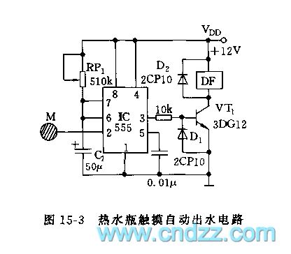
As the figure 15-3 shows, this circuit uses the 555 as the core to form the monostable trigger device. When the hand touchs the sequin M, the thermos will drain automaticly.
The monostable timing circuit is composed of the 555 and RP1,C1, the timing time td=1.1RP1C1, by adjusting RP1, you can change the drain time, the longest drain time is 10s. You should adjust it before using. The VT1 can be used to drive the electromagnetic valve DF's amplifier, the VT1 will conduct in the timing time, so the coil of the electromagnetic valve gets power, the valve rod moves down under the effect of the magnetic force to increase the horizontal pressure, then the hot water gets out from the water outlet.
(View)
View full Circuit Diagram | Comments | Reading(1062)
| Pages:1823/2234 At 2018211822182318241825182618271828182918301831183218331834183518361837183818391840Under 20 |
Circuit Categories
power supply circuit
Amplifier Circuit
Basic Circuit
LED and Light Circuit
Sensor Circuit
Signal Processing
Electrical Equipment Circuit
Control Circuit
Remote Control Circuit
A/D-D/A Converter Circuit
Audio Circuit
Measuring and Test Circuit
Communication Circuit
Computer-Related Circuit
555 Circuit
Automotive Circuit
Repairing Circuit