
Circuit Diagram
Index 1830
8156 type Amoi DVD power supply circuit
Published:2011/5/30 3:13:00 Author:Christina | Keyword: Amoi, DVD, power supply

The 8156 type Amoi DVD power supply circuit is as shown:
(View)
View full Circuit Diagram | Comments | Reading(2888)
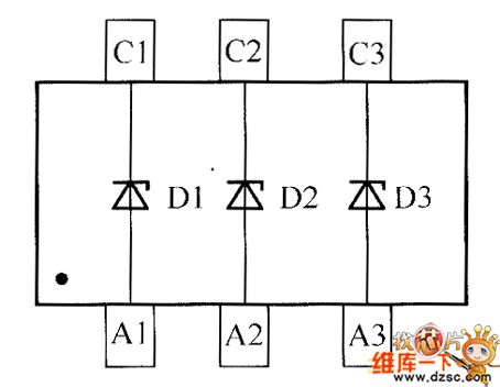
crystal diode DDZX9713T internal circuit
Published:2011/5/30 5:10:00 Author:chopper | Keyword: crystal diode, internal

View full Circuit Diagram | Comments | Reading(465)
crystal diode DDZX9714T internal circuit
Published:2011/5/30 5:09:00 Author:chopper | Keyword: crystal diode, internal
View full Circuit Diagram | Comments | Reading(420)
crystal diode DDZX9715TS internal circuit
Published:2011/5/30 5:08:00 Author:chopper | Keyword: crystal diode, internal

View full Circuit Diagram | Comments | Reading(385)
fast summing amplifier with low input current circuit
Published:2011/5/29 21:43:00 Author:chopper | Keyword: fast summing amplifier, low input current

View full Circuit Diagram | Comments | Reading(792)
LF347/LF147 quad operational amplifier circuit
Published:2011/5/29 7:39:00 Author:chopper | Keyword: quad operational amplifier

View full Circuit Diagram | Comments | Reading(813)
optical coupling V/F converter circuit
Published:2011/5/29 7:37:00 Author:chopper | Keyword: optical coupling, V/F converter

This circuit can convert 0~10V input voltage into corresponding frequency from the output end of optoisolator.When Convertor RM4151 and quad operational amplifier use together, they will has a high linearity.Quad operational amplifier,integraph,voltage regulator and LED driver.
(View)
View full Circuit Diagram | Comments | Reading(1732)
4W switch-type 5V regulated DC power supply circuit
Published:2011/5/29 7:25:00 Author:chopper | Keyword: 4W, switch-type, 5V, regulated DC power supply

View full Circuit Diagram | Comments | Reading(1245)
input protection with optoelectronic isolator circuit
Published:2011/5/29 7:11:00 Author:chopper | Keyword: optoelectronic isolator, input protection

This circuit combines diode and transistor together.When the input voltage is between 3 and 30V,the incoming current of LED of the optoelectronic isolator MOC3011 is limited to a secure ultimate value that is less than 15mA.If the polarity is set reversely by accident,this circuit can also protect the LED.
(View)
View full Circuit Diagram | Comments | Reading(570)
Analog isolation circuit
Published:2011/5/29 22:07:00 Author:chopper | Keyword: Analog, isolation

This circuit is a FM transmission system which uses light as media.The transmitter uses 565 phase-locked loop as voltage controlled oscillator,making the LED of optoelectronic isolator flash at a rate that is proportional to input voltage.The driving amplifier of photoduodiode is of enough gain to add 200mV(peak-peak) signal to the input end of recipient 565.Recipient 565 is acted as a frequency modulation detector and reproduces the signal which is imported to the transmitter.The power source is between ±6 and ±12V.
(View)
View full Circuit Diagram | Comments | Reading(2165)
F4558 operational amplifier circuit
Published:2011/5/29 7:26:00 Author:chopper | Keyword: operational amplifier

View full Circuit Diagram | Comments | Reading(11647)
The optoelectronic isolation circuit between TTL and relay
Published:2011/5/28 0:43:00 Author:chopper | Keyword: TTL, relay, optoelectronic isolation circuit

In this circuit,it uses photocoupler to make the circuit between TTL and relay gain the isolation of 100GΩ,and eliminates the effect to TTL circuit from noise of relay as well as spike voltage.When the input signal of TTL is high,Q1 is conducted,and LED has no current.And there is no light incidenting to detectors.At this time,photoelectric diode has the bigest resistance value of 5GΩ.Therefore,Q2 is inconductive,so is Q3.Thus,no current passes through the coil of relay.
(View)
View full Circuit Diagram | Comments | Reading(991)
Optical electronic potentiometer circuit
Published:2011/5/20 5:36:00 Author:chopper | Keyword: Optical electronic, potentiometer

View full Circuit Diagram | Comments | Reading(1989)
difference amplifier circuit
Published:2011/5/28 0:54:00 Author:chopper | Keyword: difference amplifier

View full Circuit Diagram | Comments | Reading(865)
crystal diode DDZX9699TS internal circuit
Published:2011/5/28 0:51:00 Author:chopper | Keyword: crystal diode, internal

View full Circuit Diagram | Comments | Reading(365)
LM324 four-Stage Amplifier circuit
Published:2011/5/28 0:27:00 Author:chopper | Keyword: four-Stage Amplifier


Four-Stage Amplifier circuit ,14 pins dual-in-line package filter is shown as follows.Active band-pass filter circuit is shown as follows:
Spectrum analyzer of acoustics uses this circuit as band-pass filter to select different signals from different frequency ranges,and indicates the scope of signals by using the amount of dots on a monitor lighted by LED.The circuit is shown as follows:
(View)
View full Circuit Diagram | Comments | Reading(6138)
PIC16C54 main control panel of air conditioning circuit
Published:2011/5/28 0:57:00 Author:chopper | Keyword: main control panel, air conditioning
View full Circuit Diagram | Comments | Reading(691)
555 simple light controller circuit
Published:2011/5/21 7:25:00 Author:TaoXi | Keyword: simple, light controller

As the figure 17-38 shows, this circuit uses the 555 as the core, and the RS trigger circuit is composed of the 555, the photosensitive tube (3DU type) and the RP. At night, the resistance between 3DU tube's c electrode and e electrode is so large, pin-2's potential closes to the ground potential, 555 sets, pin-3 has the high level voltage, and the light turns on; during the day, there is the illumination, so the resistance between 3DU tube's c electrode and e electrode reduces, pin-6's voltage exceeds the threshold level 2/3VDD, 555 resets, the light turns off.
(View)
View full Circuit Diagram | Comments | Reading(513)
The 555 multi-functional ceiling fan controller circuit
Published:2011/5/28 21:24:00 Author:Borg | Keyword: multi-functional ceiling fan
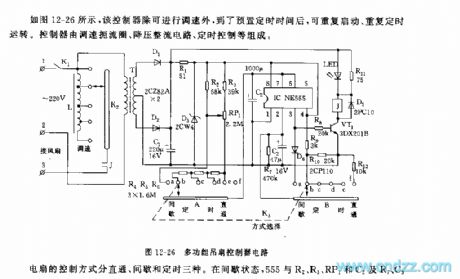
The fan control method is classified into three ways that are direct, interval and timing. In the interval state, 555,R2,R3,RP1,C2,R7,C3 and so on consists a non-steady multi-resonate oscillator, before the charging voltage reaches the trigger LEV(2/3VDD), the 3-pin of 555 is in a high LEV, VT1 is conducting, the relay J pulls in, the fan gets power and starts to run, the running time is determined by R2,R3,RP1 and C2, in the figure, the corresponding time to the parameters is around 25~60s. The interval time means the period after 555 is reset, and C2 discharges(with the help of R7) to the the trigger LEV of 2-pin(1/3VDD), the time span corresponding to the parameter in the figure is about 20s. (View)
View full Circuit Diagram | Comments | Reading(771)
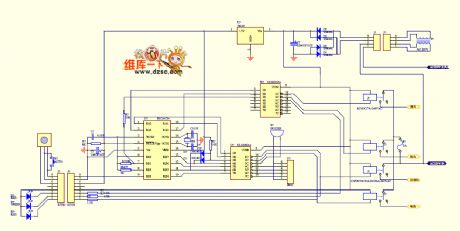
Electric Energy Metering System Simplified (Single-Phase Electric Energy Metering System AD7551) Circuit
Published:2011/5/21 1:39:00 Author:Robert | Keyword: Electric Energy, Metering System, Single-Phase

The electric energy metering system simplified circuit is shown in the picture below which is made up by AD7551 and the 89C51 MCU. C1~C4 are +5V power decoupling capacitor. The R-nor port is connected with the UDD through a pull-up resistance R1 to make the R-nor port be 1 and the reset port disabled. The 3.679545MHz crystal and capacitor C5, C6 are made up oscillation circuit to provide the timing signals to AD7751. C7 is the denoising capacitor of Uref(i/o) port.
(View)
View full Circuit Diagram | Comments | Reading(2580)
| Pages:1830/2234 At 2018211822182318241825182618271828182918301831183218331834183518361837183818391840Under 20 |
Circuit Categories
power supply circuit
Amplifier Circuit
Basic Circuit
LED and Light Circuit
Sensor Circuit
Signal Processing
Electrical Equipment Circuit
Control Circuit
Remote Control Circuit
A/D-D/A Converter Circuit
Audio Circuit
Measuring and Test Circuit
Communication Circuit
Computer-Related Circuit
555 Circuit
Automotive Circuit
Repairing Circuit