
Circuit Diagram
Index 1824
555 gas stove flameout sound & light alarm circuit
Published:2011/6/1 2:05:00 Author:TaoXi | Keyword: 555, gas stove, flameout, sound, light, alarm circuit

The electronic switch is composed of the VT1,R1 and VT2,R2. VT1 uses the phototransistor 3DU series devices, you need to put it on the horizontal plane that is about 25cm away from the stove. When the fire is normal, the VT1 is in the low resistance state, the VT2 is in the positive bias state, the pipe pressure drop is only about 0.3V, this makes the pin-4 of IC(555) in the state of forced reset -- the quiescent state.
The astable multivibrator is composed of the 555 and R3,R4,C1.etc, the oscillation frequency fc=1.44/(R3+2R4)C1. The parameters are designed according to 1000Hz.
VT1 uses the 3DU series devices such as the 3DU5, 3DU6, 3DU212.etc.
(View)
View full Circuit Diagram | Comments | Reading(560)
555 automatic AC voltage stabilizer circuit
Published:2011/6/1 2:20:00 Author:TaoXi | Keyword: 555, automatic, AC, voltage stabilizer

As the figure 15-9 shows, the voltage stabilizer circuit is composed of the voltage stabilizer part and protection part. When the input AC voltage is in the range of 160V~250V, the output voltage will be 220+/-10%, when the output voltage is more than 250V, the circuit will cut off the load automaticly; when the outage happens, the protector will automatic delay about six minutes, then turns on the power.
The two same composite amplifier is composed of the VT1, VT2, VT3, VT4 and some capacitance resistance elements. Their input signals were taken from the different contacts of the self-coupling transformer, after the rectification and pressure separate, they add to the base electrodes of the VT1 and VT3. When the input voltage is lower than 190V, the J1, J2 are not action.
(View)
View full Circuit Diagram | Comments | Reading(5218)
555 automatic home appliance protector circuit
Published:2011/6/1 2:32:00 Author:TaoXi | Keyword: 555, automatic, home appliance, protector

As the figure 15-8 shows, the protector is composed of the step-down rectifier circuit, the over-voltage under-voltage detection circuit and the delay switch control circuit. This circuit has some points of features such as the large power control, over-voltage (250V) and under-voltage (170V) protection , and the 5 minutes power-off delay.
The over-voltage under-voltage detection circuit is composed of the R2,R3,RP1,R4 and RP2, and the over-voltage under-voltage trigger circuit is composed of the over-voltage under-voltage detection circuit and the IC1(555). In the power supply voltage is normal, the IC1 outputs the rectangular wave, this wave is rectified by D9,D10, then establish the positive DC voltage on C5 to conduct the power switch integrated circuit IC2 (TWH8778), then the SCR is in the state of trigger conduction, the socket has the electricity.
(View)
View full Circuit Diagram | Comments | Reading(793)
555 sound control lighting electronic wall clock circuit
Published:2011/6/1 4:04:00 Author:TaoXi | Keyword: 555, sound control, lighting, electronic, wall clock

As the figure 15-33 shows, the circuit is composed of the voice sensor, the monostable trigger, the counter and the timing circuit.etc.
The voice sensor uses the electret condenser microphone, when you clap three times, the sound will be amplified by VT1, then triggers the monostable timing circuit which is composed of the left part (1/2 56) of the IC1 and the R5, C4, the output pulse-width td=1.1R5C4, it is about 1.2s. The IC2 uses the octonary number system count/pulse dispenser, when you clap three times, the pin-3 of 555 will output three pulses to make the pin-1, pin-3, pin-7 of IC2 have the high electrical level one by one, the VT3 conducts, the low potential of the c electrode resets the IC1, the audio signal is sealed.
(View)
View full Circuit Diagram | Comments | Reading(768)
555 multi-function appliance socket circuit (1)
Published:2011/6/1 3:06:00 Author:TaoXi | Keyword: 555, multi-function, appliance, socket
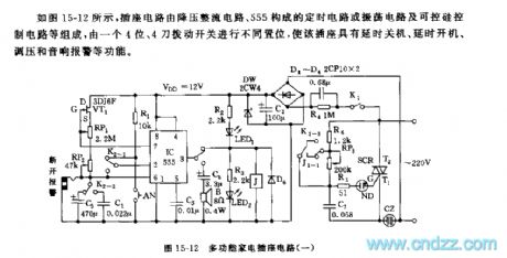
As the figure 15-12 shows, the socket circuit is composed of the step-down rectifier circuit, the timing circuit or oscilation circuit which is composed of the 555, and the silicon-controlled rectifier control circuit.etc, this circuit is set by a 4-bit, 4 knives switch, this socket has the function of delay shutdown, delay starting up, voltage adjustment and sound alarm.
The step-down rectifier circuit supplies the voltage of VDD=+12V to the controller. If you cut off K1 and dial down the K2-3, then adjust RP3, so you can adjust the conduction angle of the SCR and adjust the output voltage.
The 555 and R4,RP1,RP2,C3,C4,VT1 can form the timing boot or timing shutdown circuit, also they form the constant-current source recharging Much harmonic oscillator and the sound alarm circuit.
(View)
View full Circuit Diagram | Comments | Reading(536)
555 multi-function appliance socket circuit (2)
Published:2011/6/1 3:27:00 Author:TaoXi | Keyword: 555, multi-function, appliance, socket
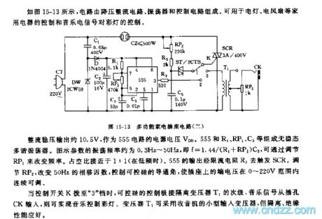
As the figure 15-13 shows, the circuit is composed of the step-down rectifier circuit, the oscillator and the control circuit. This circuit can be used in wide range of applications such as the electric lamp control, the electric fan control and the color lights control.
The rectifier voltage stabilization output is about 10.5V, this output can be used as the 555 circuit's power supply voltage VDD. The astable multivibrator is composed of the 555 and R1, RP1, C3. The figure parameters' oscillation frequency is about 0.3Hz~50Hz, f=1.44/(R1+RP1)C3, you can change the frequency by adjusting the RP1. The duty ratio is about 1:1. The output of 555 triggers the SCR through the current limiting resistor R2. By adjusting RP2 and changing the 50Hz phase shift factors, you can control the conduction angle of the SCR to make the terminal voltage in the range of 0~220V.
(View)
View full Circuit Diagram | Comments | Reading(475)
555 multi-function power supply socket circuit
Published:2011/6/1 3:52:00 Author:TaoXi | Keyword: 555, multi-function, power supply, socket
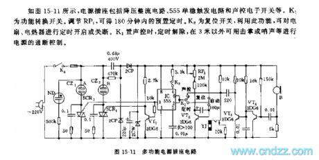
As the figure 15-11 shows, the power supply socket is composed of the step-down rectifier circuit, the 555 monostable trigger circuit and the sound control electronic switch.etc. K1 is the function conversion switch. You can get the preset timing in 180 minutes by adjusting RP1. K2 is the reset switch, you can timing open or close the fans and electric heaters by using K2. When K1 is on the sound control gear, the timing is removed, you can control the power supply on-off by the clapping or whistle three meters away.
(View)
View full Circuit Diagram | Comments | Reading(508)
555 ding-dong audio electronic doorbell circuit
Published:2011/6/1 4:04:00 Author:TaoXi | Keyword: 555, ding-dong, audio, electronic, doorbell

This two-tone bell circuit uses one piece of 555 time base circuit as the core. It sends out the beautiful and sweet sound of dingdong . The circuit is as shown in figure 15-46.
The multivibrator is composed of the 555 and R1~R3,D1,D2,C2. SA is the button switch of the door, it is usually in the disconnect state. When SA is closing, pin-4 of 555 has the low electric potential to keep it in the mandatory reset state, pin-3 outputs the low electric potential. When someone presses the SA, the power supply VDD will charge the C1 through SA and D1, pin-4 of 555 has the high electric potential, the 555 starts working, the vibration frequency fc1=1.44/(RD+2R3)C2.
RD is the DC resistance of D1 and D2.
(View)
View full Circuit Diagram | Comments | Reading(3171)
555 electric rice cooker automatic controller circuit
Published:2011/6/1 19:10:00 Author:TaoXi | Keyword: 555, electric, rice cooker, automatic controller

As the figure 15-31 shows, the controller is composed of the step-down voltage circuit (VDD=+12V), the R-S trigger circuit which is composed of 555 and the relay control circuit.etc.
The R-S trigger is composed of the 555 and R5, R6, RP1, RT, R4, RP2, VT2. RT is the negative temperature coefficient thermistor. When the cooker is cooking the dry rice, the two-knife single-throw switch K1 closes. So the separate voltages of R5 and R6 make the pin-6 of 555 gets the voltage of 2/3VDD=8V, the voltage of pin-2 is the separate voltage of RP1, RT, RP2, the voltage value is less than 1/3VDD, so 555 sets, LED1 turns on and J1 closes.
(View)
View full Circuit Diagram | Comments | Reading(836)
the circuit of soil humidity monitor part 2
Published:2011/6/1 6:40:00 Author:Ariel Wang | Keyword: soil , humidity, monitor
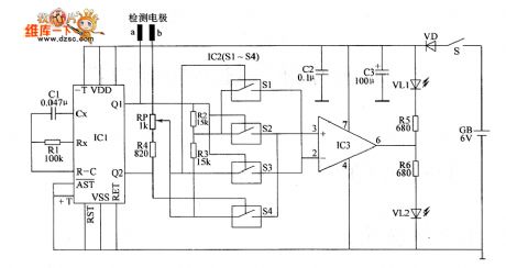
When mains switch S got through,actable multivibrator vibrates(the vibration frequency is 58Hz).From Q1 end to Q2 end of IC1,it alternately outputs high level and low level.When the Q1 end of IC1 outputs high level,the Q2 end of Q2 end outputs low level,the internal electronic switch S2 is connected with S3;when the Q2 end of IC1 outputs high level,the Q2 end of Q2 end outputs low level,the internal electric switch 51 is connected with 54.The reference voltage is generated by the branch voltage after R2 and R3 in series.It adds to 2nd-pin (reversed-phase input end) and 3rd-pin(normal phase input end) of IC3 by electronic switch S1. (View)
View full Circuit Diagram | Comments | Reading(447)
555 disabled person three-purpose electronic circuit
Published:2011/5/25 4:05:00 Author:TaoXi | Keyword: 555, disabled person, three-purpose, electronic circuit
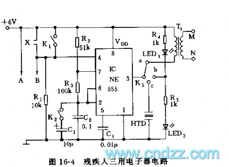
As the figure 16-4 shows, the three-purpose electronic circuit uses the 555 as the core, it has the following functions:
Wake-up function: X connects to the electronic alarm clock chip, in peacetime X is the opening circuit, K3 is in the position of contact point a. When the timing time is up, X adds the voltage to pin-4, so 555 starts working, the oscillation frequency f1=1.44/(R2+2R3)C2.
Eyesight exercise: if you close K1 and K2, then move K3 to the b contact point, so 555 forms the multivibrator which has the frequency of 1Hz, the figure parameter's oscillation frequency is about 1Hz.
The blind man water detection alarm: if you disconnect K1 and K2, and move K3 to the C port, then install A, B at the bottom of the cane, when you are working, if the bottom of the cane contacts the water, pin-4 has the high electric potential to make 555 in the oscillation state.
(View)
View full Circuit Diagram | Comments | Reading(650)
555 safe and reliable intermittent electric heating control circuit
Published:2011/5/30 18:41:00 Author:TaoXi | Keyword: 555, safe, reliable, intermittent, electric heating, control circuit

This heating circuit uses the light/electric type solid-state relay and it is composed of the step-down rectifier circuit, the duty ratio adjustable multivibrator and the solid-state relay, as the figure 15-39 shows.
The step-down rectifier circuit is composed of the buck capacitor C5, the full bridge rectifier QD and the filter capacitor C4, and it is stabilized by the three ports stabilizer IC2(7809), then it outputs the voltage of +9V to supply power to the control circuit.
The heating circuit uses the time base circuit 555 as the core, the duty ratio adjustable low-frequency multivibrator is composed of the 555 and R1,R2,RP1,D1,D2, the oscillation period is the fixed value, but the duty ratio can be adjusted by RP1.
(View)
View full Circuit Diagram | Comments | Reading(721)
555 shock vibration alarm circuit
Published:2011/5/30 9:48:00 Author:TaoXi | Keyword: 555, shock vibration, alarm
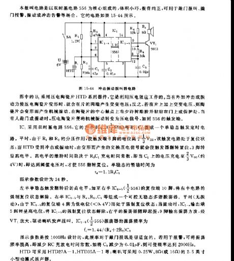
This alarm circuit uses the double time base circuit 556 as the core, it has some points of features: small size, pure report sound, and it can be used in wide range of applications such as the knocking door alarm, the breaking door alarm, the vibration or shock warning. The circuit is as shown in figure 15-44.
The IC1 uses the double time base circuit 556, the monostable trigger timing circuit is composed of it's left part IC1-a(1/2 556) and R3, C1. In peacetime, the partial pressure effect makes the trigger port pin-6's electric potential higher than 1/3VDD, and this trigger circuit is in the reset state. When HTD is impacted or oscillated, the exchange piezoelectric signal which is produced by the deformation will make the trigger to flip and set, pin-3 has the high electrical level.
(View)
View full Circuit Diagram | Comments | Reading(1076)
555 safe iron frame circuit
Published:2011/5/30 18:53:00 Author:TaoXi | Keyword: 555, safe, iron, frame

As the figure 15-2 shows, the circuit is composed of the step-down voltage rectifying circuit, the timer control circuit and the audio circuit.etc. When the electric iron is on the frame, the weight of iron presses the button AN, so IC2's trigger port pin-6 gets the partial voltage of R1 and R2, and this voltage is higher than 2/3VDD trigger electrical level, 555 resets, pin-3 has the low electrical level. IC3 is set because pin-2 has the low electrical level, pin-3 has the high electrical level, the relay J closes, and also the J1-1 twin contact points, so the electric iron has power to heat. When you pick up the iron, the C3 which has be charged discharges through R2, when the voltage is lower than pin-2's trigger electrical level 1/3VDD, 555 sets, pin-3 has the high electrical level.
(View)
View full Circuit Diagram | Comments | Reading(1681)
555 simple practical earthquake alarm circuit
Published:2011/5/30 21:08:00 Author:TaoXi | Keyword: 555, simple, practical, earthquake, alarm circuit
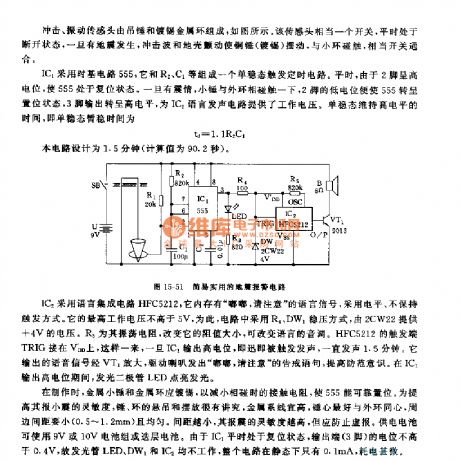
The earthquake alarm circuit is composed of the shock vibration sensor, the monostable timing circuit and the voice alarm circuit.etc, as the figure 15-51 shows. This circuit has the function of sound & light alarm to the earthquake which is more than 4 class in the medium or short distance.
The IC1 uses the time base circuit 555, the monostable trigger timing circuit is composed of the 555 and the R2,C1. In peace time, the pin-2 has the high electric potential to make the 555 in the reset state. If the earthquake happens, the hammer touches with the outer phase, pin-2's low electric potential makes the 555 in the set state,pin-3 outputs the high electric potential to supply the power to IC2 voice generating circuit. The monostable temporary stabilization time td=1.1R2C1.
(View)
View full Circuit Diagram | Comments | Reading(1707)
555 electronic language model reception circuit
Published:2011/6/1 18:49:00 Author:TaoXi | Keyword: 555, electronic, language, model, reception circuit
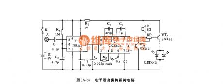
As the figure 15-37 shows, the circuit is composed of the monostable trigger and the language integrated audio circuit, and this circuit can be used in the shop and restaurant.etc.
The monostable trigger is composed of the 555 and R1, C2, when the guest touches the sequin A, the 555 circuit sets, pin-3 has the high electrical level to trigger IC2. IC2 is the language integrated circuit ICI5603 (or NS268.etc.), if pin-2 has the trigger electrical level signal, the internal memory starts working and sends out the voice of you are welcome through the speaker. At the same time the two LEDs turn on. When the 555 temporary state is finished, pin-3 has the low electrical level, the circuit is in quiet.
(View)
View full Circuit Diagram | Comments | Reading(482)
555 multi-function digital control lock circuit
Published:2011/6/1 4:28:00 Author:TaoXi | Keyword: 555, multi-function, digital control, lock circuit

As the figure 15-20 shows, the multi-function digital control lock uses the digital control lock ASIC LS7225 as the core, and this control lock circuit is composed of the trigger timing circuit, the audio circuit and some RC components.
The IC1 uses the digital control lock ASIC LS7225, it's output port function diagram is as shown in figure (b). If you press the wrong password, the 555 has the high electric potential, and this electric potential is paraphased by VT1 to set the IC3, the J2 closes to open the IC4(KD9561) sound alarm circuit and the radio transmitting circuit, they send out the ear-piercing alarm or transmit the FM. If you use the wireless receiver, you should turn the high-frequency carrier wave in the amateur band such as 88~108MHz.
(View)
View full Circuit Diagram | Comments | Reading(574)
the circuit of tv signal switching amplified principle
Published:2011/6/1 9:20:00 Author:Ariel Wang | Keyword: tv, signal, switching amplified, principle

The circuit of tv signal switching amplified principle can be seen as the chart.
(View)
View full Circuit Diagram | Comments | Reading(468)
the amplified circuit of an improved Durestos All-Channel Antenna
Published:2011/6/1 9:25:00 Author:Ariel Wang | Keyword: amplified, improved, Durestos, All-Channel , Antenna

The amplified circuit of an improved Durestos All-Channel Antenna can be seen as the chart.
(View)
View full Circuit Diagram | Comments | Reading(575)
555 electronic cane circuit
Published:2011/6/1 18:59:00 Author:TaoXi | Keyword: 555, electronic cane

As the figure 15-38 shows, the electronic cane circuit is composed of a 555 circuit, a audio integrated circuit KD-9561 and the mercury switch.etc. It has two functions: alarm and lighting, it is small and exquisite.
When people with this electronic cane fall down, the mercury switch K1 opens, the power supply adds to the two integrated blocks. The trigger circuit is composed of the 555 and R1, R2, C1. Once the K1 opens, because the C1's voltage can not be changed, so the 555 sets, it's pin-7 has the high resistance to conduct VT1, so the alarm sound of the KD-9561 is sent out by the YD electromagnetic signal response device to call people for help.
(View)
View full Circuit Diagram | Comments | Reading(566)
| Pages:1824/2234 At 2018211822182318241825182618271828182918301831183218331834183518361837183818391840Under 20 |
Circuit Categories
power supply circuit
Amplifier Circuit
Basic Circuit
LED and Light Circuit
Sensor Circuit
Signal Processing
Electrical Equipment Circuit
Control Circuit
Remote Control Circuit
A/D-D/A Converter Circuit
Audio Circuit
Measuring and Test Circuit
Communication Circuit
Computer-Related Circuit
555 Circuit
Automotive Circuit
Repairing Circuit