Automotive Circuit
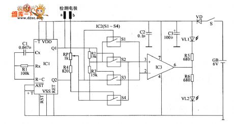
the circuit of soil humidity monitor part 2
Published:2011/6/1 6:40:00 Author:Ariel Wang | Keyword: soil , humidity, monitor | From:SeekIC

When mains switch S got through,actable multivibrator vibrates(the vibration frequency is 58Hz).From Q1 end to Q2 end of IC1,it alternately outputs high level and low level.When the Q1 end of IC1 outputs high level,the Q2 end of Q2 end outputs low level,the internal electronic switch S2 is connected with S3;when the Q2 end of IC1 outputs high level,the Q2 end of Q2 end outputs low level,the internal electric switch 51 is connected with 54.The reference voltage is generated by the branch voltage after R2 and R3 in series.It adds to 2nd-pin (reversed-phase input end) and 3rd-pin(normal phase input end) of IC3 by electronic switch S1.
Reprinted Url Of This Article:
http://www.seekic.com/circuit_diagram/Automotive_Circuit/the_circuit_of_soil_humidity_monitor_part_2.html
Print this Page | Comments | Reading(3)

Article Categories
power supply circuit
Amplifier Circuit
Basic Circuit
LED and Light Circuit
Sensor Circuit
Signal Processing
Electrical Equipment Circuit
Control Circuit
Remote Control Circuit
A/D-D/A Converter Circuit
Audio Circuit
Measuring and Test Circuit
Communication Circuit
Computer-Related Circuit
555 Circuit
Automotive Circuit
Repairing Circuit
Code: