
Circuit Diagram
Index 1833
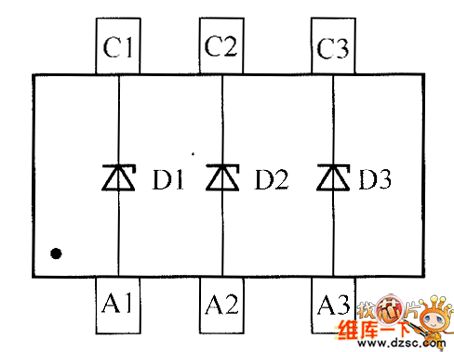
crystal diode DDZX9712TS internal circuit
Published:2011/5/29 22:08:00 Author:chopper | Keyword: crystal diode, internal

View full Circuit Diagram | Comments | Reading(375)
crystal diode DDZX9709TS internal circuit
Published:2011/5/29 21:46:00 Author:chopper | Keyword: crystal diode, internal
View full Circuit Diagram | Comments | Reading(339)
TDA2030 typical application circuit
Published:2011/5/29 21:45:00 Author:chopper | Keyword: typical application


View full Circuit Diagram | Comments | Reading(1489)
crystal diode DDZX9708TS internal circuit
Published:2011/5/29 21:38:00 Author:chopper | Keyword: crystal diode, internal

View full Circuit Diagram | Comments | Reading(366)
Direct FM Modulation Circuit Composed of Variable Capacitance Diode
Published:2011/5/25 4:47:00 Author:Joyce | Keyword: Direct FM Modulation, Variable Capacitance Diode

View full Circuit Diagram | Comments | Reading(617)
Annular Modulation Circuit
Published:2011/5/25 4:49:00 Author:Joyce | Keyword: Annular , Modulation

View full Circuit Diagram | Comments | Reading(487)
555 electronic eyesight protector circuit
Published:2011/5/23 21:53:00 Author:TaoXi | Keyword: electronic, eyesight protector
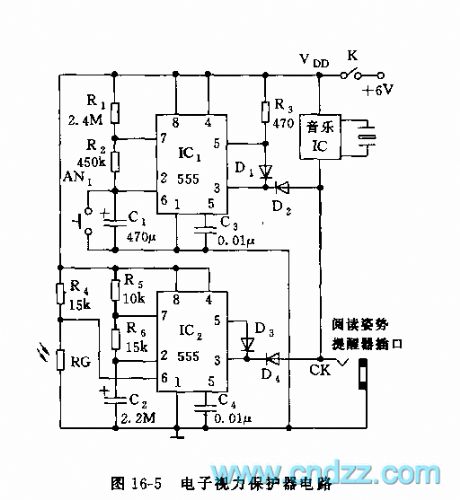
As the figure 16-5 shows, the protector is composed of the reading time limit reminder and the reading environment metering device, and it can be used to protect the students' eyesight.
The multivibrator is composed of the IC1(555) and the R1, R2, C1, the oscillation period T=tcharging+tdischarging, when you are using it, press the AN1, the 555 sets, at the same time, C1 is charged by R1 and R2, the time of charging is about 50 minutes, tcharging=0.693(R1+R2)C1. When pin-6's electrical level is 2/3VDD, the 555 reverses and resets, the pin-3 has the low electrical level, the music IC sends out the voice to remind you to have a rest.
The reading environment metering device is composed of the IC2, R5,R6,C2, R4 and the photoresistor RG, when the reading light intensity is lower than 100 lux, the value of RG becomes higher.
(View)
View full Circuit Diagram | Comments | Reading(467)
555 high voltage generator circuit
Published:2011/5/23 20:43:00 Author:TaoXi | Keyword: high voltage, generator circuit

As the figure 16-18 shows, the high voltage generator uses the 555 as the core, the oscillation voltage is boosted by the step-up transformer. The astable multivibrator is composed of the 555 and R1,R2,C1, the oscillation frequency f=1.44/(R1+2R2)C1, it is about 2000Hz. The 555 oscillation square-wave is amplified by VT1, and is boosted by transformer T1, an then it is rectified by the high-pressure reactor D1, at last we get the 3-5kV DC voltage. The D1 reverse breakdown voltage is higher than 15 kV, VT1's Vced>50V. The transformer T1 outputs the transformer ignition coil by using the 9-12 inches television. The secondary coil is binded by 30 turns of high strength enameled wire with the diameter of 0.6mm.
(View)
View full Circuit Diagram | Comments | Reading(6362)
555 electronic ballast circuit
Published:2011/5/24 2:52:00 Author:TaoXi | Keyword: electronic, ballast
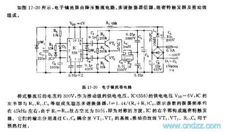
As the figure 17-20 shows, the electronic ballast is composed of the step-down rectifier circuit, the multivibrator source circuit, the Schmitt trigger and the promotion stage.
The bridge rectifying voltage is 300V, and this voltage is used as the promotion stage's power supply voltage. IC(556)'s power supply voltage VDD=6V, the left part of IC and the R6,R1,C9 constitute the astable multivibrator, the oscillation frequency f=1.44/(R6+R1)C9, the parameters of the figure's oscillation frequency is about 45kHz, because R1=R6, so the duty cycle is about 50%, it is the symmetrical square wave. The right part of the IC constitutes the Schmitt trigger.
(View)
View full Circuit Diagram | Comments | Reading(1157)
555 light control timing streetlight circuit
Published:2011/5/22 5:06:00 Author:TaoXi | Keyword: light control, timing, streetlight

The step-down rectifier circuit supplies the VDD=9V DC voltage to the control circuit, the biasing circuit of VT2 is composed of the phototransistor VT1 and R1. At night, the base electrode has no light, so c-e has the high resistance, VT2, VT3 and the switch tube VT4 conduct, IC1,IC2 get the power, the astable oscillator which is composed of the IC1(555) and R5,R6,RP1,C2 starts to work. The oscillation frequency f=1.44/(RP1+R5+R6)C2. The monostable charging circuit is composed of the IC2 and RP2,C3, the time constant Rp2C3>>T=1/f. At the beginning, the voltage of C3 is lower than 1/3VDD trigger electrical level, so IC2 sets, pin-3 has the high electrical level, SCR conducts and the street lamp H turns on.
(View)
View full Circuit Diagram | Comments | Reading(561)
555 light control street lamp switch circuit
Published:2011/5/24 2:53:00 Author:TaoXi | Keyword: light control, street lamp, switch circuit

As the figure 17-29 shows, the light control is composed of the step-down rectifier circuit, the photoconductive resistance RG and the photoelectric conversion circuit. The Schmitt trigger circuit is composed of the 555 and the RG,RP.etc. RG receives the light, so it has the low resistance about dozens of thousands of ohms; when there is no light, RG has the high resistance about dozens of megabytes of ohms. So in the daytime, pin-6 of 555 has the high electrical level, 555 resets, J releases, the street lamp H turns off; at night, RG has the high electrical level, 555 sets, J closes, the street lamp H turns on.RG uses the Cds photoconductive resistance, also it can use the phototransistor.
(View)
View full Circuit Diagram | Comments | Reading(550)
555 vegetable sterilization and detoxification machine circuit
Published:2011/5/23 19:08:00 Author:TaoXi | Keyword: vegetable, sterilization, detoxification, machine
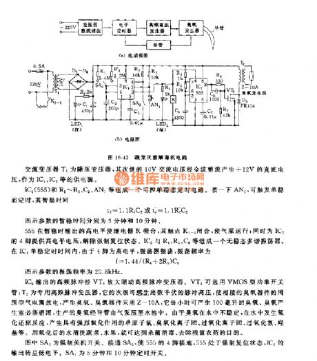
This circuit is composed of the step-down rectifier circuit, the electronic timing circuit, the high frequency oscillation high voltage circuit, the ozone generator and the antioxidant pressure pump.etc, as the figure 16-42 shows.
The AC transformer T1 is the step-down transformer, it's secondary stage has the 10V AC current, and this current is rectified by the full wave to produce the +12V DC current as the power supply of the IC1 and IC2.
The controllable monostable timing circuit is composed of the IC1(555) and R1~R3,C2,AN1.etc. By pressing AN1, you can trigger the monostable state.IC2's high-frequency pulse is amplified by VT1 to drive the high-frequency pulse transformer. The VT1 uses the VMOS type power switch tube.
(View)
View full Circuit Diagram | Comments | Reading(697)
555 light control streetlights circuit
Published:2011/5/22 9:10:00 Author:TaoXi | Keyword: light control, streetlights

As the figure 17-27 shows, the light control circuit uses the photosensitive components and the 555.etc to form the trigger circuit. In the daytime, the 2CU2B photoconductive resistance receives the illumination, so it has the low resistance, pin-6 has the high electrical level (>2/3VDD), 555 resets, J releases, CZ has no power, so the streetlight turns off; at night, the photoconductive resistance has the high resistance, pin-2's electrical level is less than 1/3VDD, 555 sets, J closes, the streetlight turns on.
(View)
View full Circuit Diagram | Comments | Reading(503)
The low-voltage starting controller circuit of 555 ceiling fans
Published:2011/5/29 19:44:00 Author:Borg | Keyword: low-voltage, starting controller
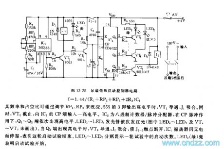
See as Figure 12-25, the low-voltage starting controller is based on two integrated circuits, which is used to do auto-control in the low-voltage starting trial of ceiling fan. 555,R1,RP1,RP2,R2 and C1 consist a non-steady multi-resonate oscillator, and the oscillating frequency is : F=1.44/(R1+RP2+RP1+2R2)C1
Figure 12-25 The low-voltage starting controller circuit of ceiling fans
The frequency and duty cycle can be changed by RP1 and RP2. When the 3-pin of 555 outputs a high LEV, VT1 is conducting and J1 is pulling in. In the meantime, VT2 is blocked and delivers a high LEV to the CP terminal of IC2. IC2 is an octal counter/pulse distributor. (View)
View full Circuit Diagram | Comments | Reading(455)
The 555 multi-functional fan controller circuit
Published:2011/5/28 21:44:00 Author:Borg | Keyword: multi-functional fan
See as figure 12-15, the controller includes the step-down rectifier circuit, time-based pulse generator, frequency distributor, high-speed starting timing circuit, wind switching circuit and controllable trigger circuit. The most noticeable character of this controller is that its rotating speed changes with the working time. When it is starting, the fan runs at a high speed, and it switches into the analog natural wind mode automatically in dozens of seconds. And the circuit can also used as a timed stepless governor. Besides, the circuit can also be used as the light adjuster, temperature controller, timer and so on of lamps and electric appliances, after it is adjusted.
(View)
View full Circuit Diagram | Comments | Reading(399)
The integrated controller circuit of 555
Published:2011/5/28 21:59:00 Author:Borg | Keyword: integrated controller
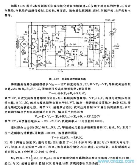
See as Figure 12-22, the controller can fulfill stepless timing and stepless speed adjusting, which can not only control fans, but also control heaters and motors, and its timing span is long and precision is high. This circuit includes the speed adjuster, timer, interval switch, chief switch and power supply,etc.
Figure 12-22 The integrated controller circuit The step down circuit provides a DC voltage of +12v for the controller. IC1, VT1~VT2 and so on consist the speed adjuster control circuit, while 555,R3,R4 and C3 consist the controllable multi-resonate oscillator, the oscillating period is T=0.693(R3+R4+RP1)C3. (View)
View full Circuit Diagram | Comments | Reading(457)
The auto controller circuit of 555 fans
Published:2011/5/28 22:12:00 Author:Borg | Keyword: auto controller
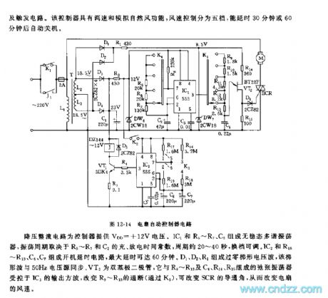
See as Figure 12-14, the controller includes the step-down rectifier circuit, low-frequency oscillator, timing circuit, controllable silicon conduction angle controller and trigger circuit. This controller has functions of speed adjusting and simulating natural wind, the wind speed is classified into 5 levels, and it can delay for 30min or 60min before the fan is power-off.
The step-down circuit offer the controller a voltage of +12V. IC1,R5~R7 and C2 consist a non-steady multi-resonate oscillator, whose oscillating period depends on the charging and discharging time parameters of R5~R7 and C2, the period ranges 20 to 40s which can be adjusted by shifting gears. (View)
View full Circuit Diagram | Comments | Reading(456)
The programme controller circuit of 555 fans
Published:2011/5/29 6:30:00 Author:Borg | Keyword: programme controller
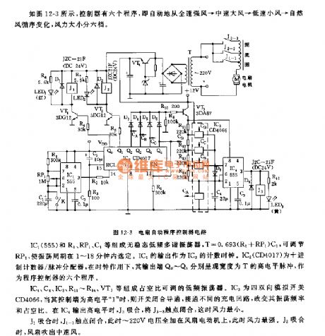
IC4,C4,IC3,R11~R14,VT3 and so on consist a low-frequency oscillator whose duty cycle can be adjustable. IC3 is a 4-two-way analog switch CD4066, when the control pole is in a high LEV 1 , the switch closes and becomes conducting, the frequency and duty cycle can be changed by connecting with different charging circuits. When IC4 outputs a high LEV, J3 pulls in and the contact of J3-3 is closed, at the moment, the wind is the weakest. When J1 pulls in, J1-1 is closing, and now all the voltage of 220V is imposed on the fan motor, so the wind is the strongest. When J2 pulls in, the fan generates intermediate speed winds. (View)
View full Circuit Diagram | Comments | Reading(481)
The temperature controller circuit of 555 fans
Published:2011/5/29 6:47:00 Author:Borg | Keyword: temperature controller
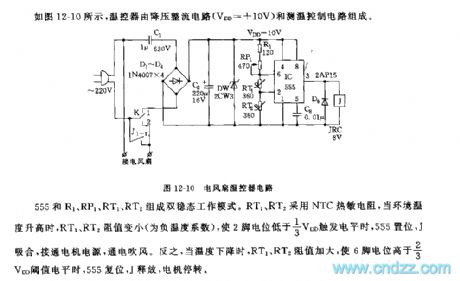
See as Figure 12-10, the temperature controller consists of the step-down rectifier circuit (VDD=+10V) and temperature detection control circuit.
555,R1,RP1,RT1 and RT2 form a dual steady working mode. RT1 and RT2 is made of NTC thermistors, when it gets hotter outside, the resistances of RT1 and RT2 turn lower(the temperature coefficient is negative), which makes the LEV on 2-pin is low than the trigger LEV of 1/3VDD and 555 is offset, J pulls in, the motor power supply is connected. Otherwise, when it's cooler outside, the resistances of RT1 and RT2 are rising,which makes the LEV of 6-pin higher than the threshold value LEV of 2/3VDD, 555 is reset and J is released, so the motor stops. (View)
View full Circuit Diagram | Comments | Reading(1404)
The interval power supply outlet circuit of 555 fans
Published:2011/5/29 7:07:00 Author:Borg | Keyword: power supply outlet
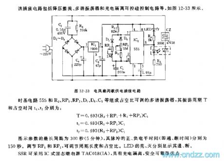
The time-based circuit 555, R2,RP1,RP2,D5,D6,C1 and so on consist a multi-resonate oscillator whose duty cycle is adjustable, the shaking period T and duty cycle times t1 and t2 are: T=0.693(R2+RP1+R3+RP2)C1 t1=0.693(R2+RP1)C1 T2=0.693(R3+RP2)C1The longest period of the figured parameter is 300s(5min), and the positive and the negative times (i.e on/off time) of the pulse are 150s,respectively. The period span and duty cycle can be adjusted by RP1 and RP2. The lighting or not of LED means on or off, respectively. SSR is fixed with IC solid relay TAC018(IA), which has advantages of photo-electricity separation and safety. (View)
View full Circuit Diagram | Comments | Reading(474)
| Pages:1833/2234 At 2018211822182318241825182618271828182918301831183218331834183518361837183818391840Under 20 |
Circuit Categories
power supply circuit
Amplifier Circuit
Basic Circuit
LED and Light Circuit
Sensor Circuit
Signal Processing
Electrical Equipment Circuit
Control Circuit
Remote Control Circuit
A/D-D/A Converter Circuit
Audio Circuit
Measuring and Test Circuit
Communication Circuit
Computer-Related Circuit
555 Circuit
Automotive Circuit
Repairing Circuit