
Circuit Diagram
Index 1826
Open-circuit state display logic pen circuit (2)
Published:2011/5/26 8:04:00 Author:Christina | Keyword: Open-circuit, state, display, logic pen

The Open-circuit state display logic pen circuit (2)
(View)
View full Circuit Diagram | Comments | Reading(594)
Lithium battery constant voltage charging circuit
Published:2011/5/30 21:21:00 Author:Fiona | Keyword: Lithium battery, constant voltage
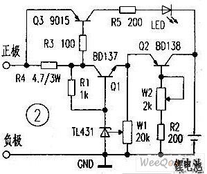
The figure below shows a constant current of the lithium battery charging control panel, the figure Q1, R1, W1, TL431 consist of the precision adjustable voltage circuit. Q2, W2, R2 consist of adjustable constant-current circuit. Q3, R3, R4, R5, LED are charging instructions circuit. With Rechargeable lithium battery's voltage rises gradually, charge current will gradually decrease,the R4 batteries voltage will continue to decrease after the battery is full finally ended Q3, LED is off, in order to ensure the battery is sufficient,please continue to charge 1 ~ 2 hours after the lights extinguished , it need to install the appropriate size of the heat sink at Q2, Q3 when using. (View)
View full Circuit Diagram | Comments | Reading(996)
Car Windshield Wiper Controller (the 3rd)
Published:2011/5/20 2:55:00 Author:Felicity | Keyword: Car Windshield Wiper Controller (the 3rd)

Work of the circuit
The circuit consists of examining circuit, Multivibrator and motor control circuit (It is showed in the picture 7-165.).
When it is rainy the Multivibrator begins to work. When the outputted signal is of high level the windshield wiper begins to work. And when the signal is of low level the motor stops working.
When the rain is not heavy the motor will just wok for a short time. And when the rain is heavy the motor will work for a rather long time. (View)
View full Circuit Diagram | Comments | Reading(1033)
Eye-care Lamps (the 1st)
Published:2011/5/20 1:49:00 Author:Felicity | Keyword: Eye-care Lamps (the 1st)
Work of the circuit
The circuit consists of power circuit, touching light adjust circuit, control execute circuit and light examine circuit (It is showed in picture 9-68.).
When hand touches pole A body inducted signal is supplied to rC’s pin 5 through resistor R5 and R6 to make circuit within IC work. The function of light examining can protect the user’s vision in case the light is too dim. (View)
View full Circuit Diagram | Comments | Reading(607)
Agricultural Automatic Water Feeder (18)
Published:2011/5/25 6:02:00 Author:Sue | Keyword: Agricultural, Automatic, Water Feeder

When the level is lower than b, D6 outputs low level, D5 outputs high level. D1-D4 output low level. VL is red. K is connected. KM is connected. M begins to feed water.
When the level reaches c, D6,D1-D4 output high level. K and KM are released. M stops working. When the level is lower, D6 outputs high level, M doesn't work. When the level is lower than b, M begins to work.
The circuit works in such a way to keep the level moving between b and c. (View)
View full Circuit Diagram | Comments | Reading(455)
Agricultural Automatic Water Feeder (17)
Published:2011/5/25 5:58:00 Author:Sue | Keyword: Agricultural, Automatic, Water Feeder

When the level doesn't reach the highest point, V2 is connected and V3 is disconnected. K is connected. M begins to feed water.
When the level reaches the highest point, V4 is connected. V3 V2 are disconnected. K is released. M stops working.
When the level reaches the low level, V1 and V2 are connected, V3 is disconnected. K is connected and M begins to work again.
The circuit works in such a way to keep the water level moving between the highest and the lowest. (View)
View full Circuit Diagram | Comments | Reading(515)
Agricultural Automatic Water Feeder (16)
Published:2011/5/25 5:55:00 Author:Sue | Keyword: Agricultural, Automatic, Water Feeder

When the level is lower than B, D4 outputs low level, RS will reverse. D3 outputs high level. V and K are connected. M begins to feed water.
When the level is higher than B, D4 outputs high level, M keeps feeding water.
When the level reaches A, IC's 1 pin has low level, RS will reverse and D3 outputs low level. V is disconnected and K is released. M stops working.
When the level is lower than A, IC's 1 pin will become high level. When the level is lower than B, the circuit works like above, keeping the level moving between A and B. (View)
View full Circuit Diagram | Comments | Reading(548)
M50431—101SP (TV)infrared remote control receiving microprocessor circuit
Published:2011/5/26 9:58:00 Author:Lena | Keyword: infrared, remote control, receiving, microprocessor
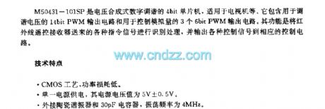
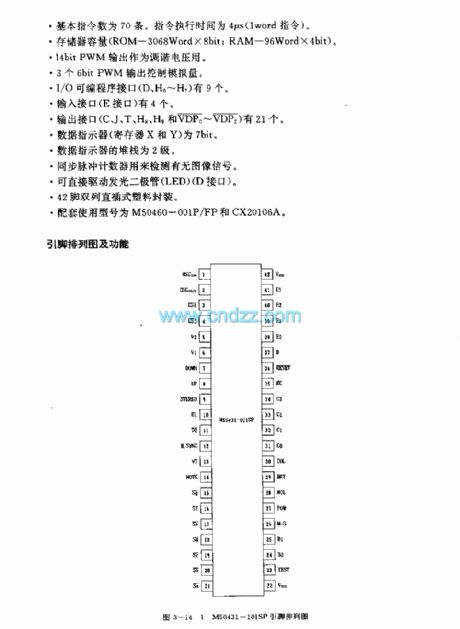
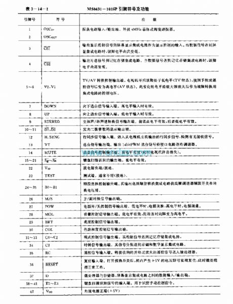
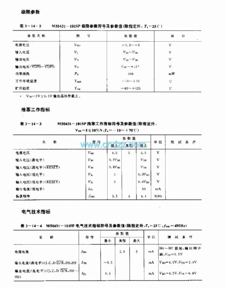
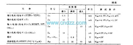
M50431-101SP is a voltage synthesis digital tuning 4-bit singlechip, applied to TV etc. It contains 14bit PWM output circuit used to tune voltage and three 6-bit PWM output circuit used to control analog quantity. The function is identifying different instruction signals sent by infrared remote control receiver, then output control signals to corresponding control circuit.
technology featureCMOS technics, power loss is low.Single power supply, the voltage value is 5V±0.5VConnectting Ceramic Resonator and 30pF capacitor, oscillation frequency is 4MHz.
(View)
View full Circuit Diagram | Comments | Reading(1407)
DC fluorescent circuit
Published:2011/5/30 0:45:00 Author:Christina | Keyword: DC, fluorescent

This circuit is composed of three components and a transformer, it has the features of simple structure, high efficiency, low power consumption and durable.
(View)
View full Circuit Diagram | Comments | Reading(488)
U disk circuit principle diagram
Published:2011/5/26 8:13:00 Author:Christina | Keyword: U disk, circuit principle

View full Circuit Diagram | Comments | Reading(589)
Integral circuit principle diagram
Published:2011/5/26 8:14:00 Author:Christina | Keyword: Integral, principle
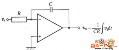
The Integral circuit principle diagram is as shown:
(View)
View full Circuit Diagram | Comments | Reading(554)
HIC1015 protection circuit
Published:2011/5/26 8:15:00 Author:Christina | Keyword: protection circuit

The HIC1015 protection circuit is as shown:
(View)
View full Circuit Diagram | Comments | Reading(837)
Crystal transistors EMD12 and UMD12N interal circuit
Published:2011/5/26 8:16:00 Author:Christina | Keyword: Crystal transistors, interal circuit
The Crystal transistors EMD12 and UMD12N interal circuit is as shown:
(View)
View full Circuit Diagram | Comments | Reading(657)
DAC0832 and 8031 double buffers synchronous way interface circuit
Published:2011/5/26 7:56:00 Author:Christina | Keyword: double buffers, synchronous way, interface circuit

View full Circuit Diagram | Comments | Reading(569)
DAC811 and 4-bit microcomputer interface circuit
Published:2011/5/26 7:59:00 Author:Christina | Keyword: 4-bit, microcomputer, interface circuit

View full Circuit Diagram | Comments | Reading(551)
Sharp C-1460 protection circuit
Published:2011/5/26 7:58:00 Author:Christina | Keyword: Sharp, protection circuit

The Sharp C-1460 protection circuit is as shown:
(View)
View full Circuit Diagram | Comments | Reading(744)
Sharp 29NF-1 protection circuit
Published:2011/5/26 2:52:00 Author:Christina | Keyword: Sharp, protection
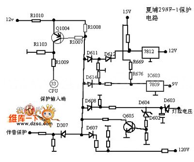
The Sharp 29NF-1 protection circuit is as shown:
(View)
View full Circuit Diagram | Comments | Reading(447)
LED tuning indication circuit
Published:2011/5/25 22:11:00 Author:Christina | Keyword: LED, tuning, indication circuit
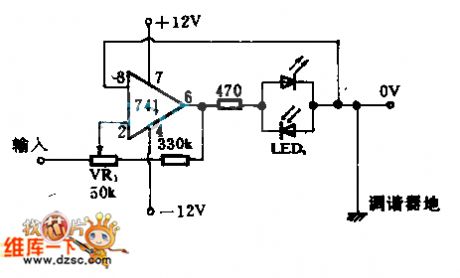
You can install a LED on the first endpoint of the tuning dish. Which light-emitting diode conducts, the tuning instruction will be away from it, when the two LEDs are all cut off, the tuning instruction will goes to dead point, so we get the right tuning instruction point.
The advantage of the tuner is the low current consumption, you can use a LED which has the weakest light to indicate the very tiny tuning error. By adjusting VR1, you can make the dead point area wide enough, so the LED will not flash because of the big volume language or music.
(View)
View full Circuit Diagram | Comments | Reading(564)
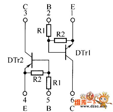
Internal circuit of the crystal transistors EMH9 and UMH9N
Published:2011/5/25 22:13:00 Author:Christina | Keyword: Internal circuit, crystal transistors
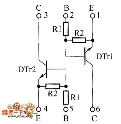
The internal circuit of the crystal transistors EMH9 and UMH9N is as shown:
(View)
View full Circuit Diagram | Comments | Reading(467)
Shanghai GM Cadillac CTS saloon car circuit
Published:2011/5/26 1:59:00 Author:Christina | Keyword: Shanghai GM, Cadillac, saloon car

The Shanghai GM Cadillac CTS saloon car circuit is as shown:
(View)
View full Circuit Diagram | Comments | Reading(426)
| Pages:1826/2234 At 2018211822182318241825182618271828182918301831183218331834183518361837183818391840Under 20 |
Circuit Categories
power supply circuit
Amplifier Circuit
Basic Circuit
LED and Light Circuit
Sensor Circuit
Signal Processing
Electrical Equipment Circuit
Control Circuit
Remote Control Circuit
A/D-D/A Converter Circuit
Audio Circuit
Measuring and Test Circuit
Communication Circuit
Computer-Related Circuit
555 Circuit
Automotive Circuit
Repairing Circuit