
Circuit Diagram
Index 1821
Water level indicator circuit (2)
Published:2011/5/26 22:30:00 Author:Christina | Keyword: Water level, indicator

Circuit operating principle
This water level indicator circuit is composed of the water level detection electrode A-E, the four two-way analog switch integrated circuit IC, the light-emitting diode VLl-VM, the resistors Rl - R9, the audio amplifier tube V and the buzzer HA.etc, as the figure shows.
The electrode A is the low water level electrode; the electrode B is the 1/4 water level electrode, the electrode C is the 1/2 water level electrode, the electrode D is the 3/4 water level electrode; the electrode E is the high water level electrode.
When the water tank's water level is 1/4, the water resistance connects the electrode A with the electrode B, pin-13 of the IC has the high electrical level, the switch S1 of the IC opens to turn on the VL1.
(View)
View full Circuit Diagram | Comments | Reading(873)
Mixed mode antenna amplifier circuit
Published:2011/5/30 2:47:00 Author:Christina | Keyword: Mixed mode, antenna amplifier

The amplification-mix mode antenna amplifier circuit is as shown in figure 1. The 1 to 12 channels TV signal is input from the VHF input port, the simple low-pass filter is composed of the L1, C1 and L2, the TV signal (filtered the channel 12) is delivered to the IC1 signal input port to accept the 20dB amplification, then the amplified TV signal is output through the capacitance C3, at last it is mixed with the UHF signal by the L3, C4, L4 low-pass filters, then it is delivered to the TV signal output port.
Figure: Mixed mode antenna amplifier circuit
The simple high-pass filter is composed of the C5, L5 and C6, it only allows the 13 channel and the raer channels of UHF band to get through. (View)
View full Circuit Diagram | Comments | Reading(871)
General infrared remote control switch
Published:2011/6/1 20:48:00 Author:Christina | Keyword: General, infrared, remote control

Working principle: the infrared remote control switch circuit is as shown in the figure. It is composed of the infrared receiving module, the triode VQ1, the D flip-flop, the driving triode VQ3, the relay, the relay working status indicator LED, the ZD1 voltage-regulator diode and the triode VQ2.etc. The infrared receiving module of the circuit detects the remote launch 37.9kHz negative pulse sequence, there negative pulses change into the positive pulses by VQ1. Then these positive pulses change into the single pulses by the R4, VD1, R5 and C2 network. The positive pulses of the VQ1 collecting electrode charge the C2 through R4 and VD1. The charging time constant (R4 X C2) is about 1.25ms. (View)
View full Circuit Diagram | Comments | Reading(914)
Optical safety switch circuit diagram
Published:2011/5/30 6:28:00 Author:Lucas | Keyword: Optical safety switch
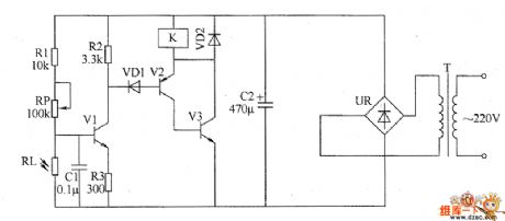
The optical safety switch circuit consists of the power supply circuit, light control circuit and control implementation circuit (switch circuit), the circuit is shown as the chart. Power circuit is composed of the power transformer T, bridge rectifier UR and filter capacitor C2. Light control circuit is composed of the photosensitive resistor RL, resistors R1 ~ R3, potentiometer RP, transistor V1 and capacitor C1. Control implementation circuit consists of the diodes VD1 and VD2, transistors V2 and V3 and the relay K. AC 220Y voltage bucked by T, filtered by UR and rectified by C2 can provide 6V DC voltage for light control circuit and control implementation circuit. R1 ~ R3 use potentiometer l/4W carbon or metal film resistors. RP selects variable potentiometer or solid film variable resistor.
(View)
View full Circuit Diagram | Comments | Reading(1543)
The inverter circuit diagram 2
Published:2011/5/30 4:31:00 Author:Lucas | Keyword: inverter
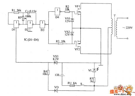
The inverter circuit consists of low-frequency oscillator, buffer and push-pull amplifier output circuit, the circuit is shown as the chart. Low-frequency oscillator is composed of two NOT gate circuits D1, D2 which is inside of NOT gate IC (D1 ~ D4), resistor R1, potentiometer RP and capacitor C. Buffer is composed of two NOT gate circuits D3, D4 which is inside of NOT gate IC (D1 ~ D4) and resistors R2, R3. Push-pull output circuit is composed of Zener diodes VS1, VS2, VM0S field-effect transistors VF1, VF2 and transformer T. Resistor R4, Zener diode VS3, diode VD and IC form the power supply circuit. Light-emitting diode V1, resistor R5 form the working indicating circuit. R1 ~ R5 use 1/4W carbon film resistors or metal film resistors.
(View)
View full Circuit Diagram | Comments | Reading(1095)
Eight-way lock electronic switch circuit diagram
Published:2011/6/1 7:00:00 Author:Lucas | Keyword: Eight-way , lock electronic switch
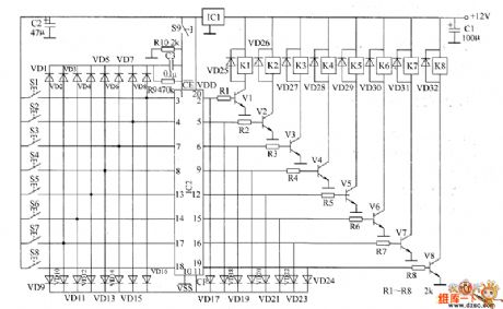
The 8-way lock electronic switch circuit is composed of the regulator filter circuit, input control circuit, latch circuit and control implementation circuit, and the circuit is shown as the chart. Regulator filter circuit is composed of the three terminal voltage regulator integrated circuit IC1 and filter capacitors C1, C2. Input control circuit consists of the control buttons S1 ~ S8, diodes VD1 ~ VD16. Latch circuit consists of eight D flip-flop integrated circuits IC2 and reset button S9, resistors R9 and R10, capacitor C3. Control implementation circuit is composed of the transistors V1 ~ V8, diodes VD17 ~ VD32, resistors R1 ~ R8 and relays K1 ~ K8. R1 ~ R10 uses 1/4W carbon film resistors or metal film resistors.
(View)
View full Circuit Diagram | Comments | Reading(1910)
± 12V voltage conversion circuit diagram
Published:2011/5/30 4:23:00 Author:Lucas | Keyword: ± 12V , voltage conversion

View full Circuit Diagram | Comments | Reading(587)
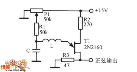
50kHz Sine wave oscillator circuit diagram
Published:2011/6/1 6:41:00 Author:Lucas | Keyword: 50kHz, Sine wave , oscillator
View full Circuit Diagram | Comments | Reading(820)
Temperature centralized controller circuit diagram
Published:2011/6/1 7:09:00 Author:Lucas | Keyword: Temperature, centralized controller

The temperature centralized controller circuit consists of the power supply circuit and temperature control circuit, and the circuit is shown as the chart. The power circuit is composed of the power switch SO, fuse FUO, power transformer T, brigde rectifier UR, filter capacitors C1 and C2, three-terminal regulator integrated circuit IC, current-limiting resistor RO and power indicator LED VLO. Temperature control circuit is composed of the relays K1 ~ Kn, thermal relay sKR1 ~ KRn, resistors R01 ~ R0n, R1 ~ Rn, thyristors VT1 ~ VTn, fuses FU1 ~ FLn, heater case power switches S1 ~ Sn, electric heater(heater case,electric heater), EH1 ~ EHn and work instructor LEDs VL1 ~ VLn. RO ~ Rn and R01 ~ R0n use 1/4W carbon film resistors or metal film resistors.
(View)
View full Circuit Diagram | Comments | Reading(570)
CMOS control signal circuit diagram
Published:2011/6/1 19:50:00 Author:Lucas | Keyword: CMOS , control signal

CMOS control circuit is a pulse-width modulation (PWM) circuit, PWM waveform is mainly composed of the CD4001 NOR gate circuit and CD4013 D flip-flop, and the circuit is shown as the chart.
(View)
View full Circuit Diagram | Comments | Reading(1369)
DC voltage-stabilizing circuit diagram
Published:2011/6/1 19:47:00 Author:Lucas | Keyword: DC , voltage-stabilizing

The DC voltage-stabilizing circuit in the power supply system is shown as the figure, 170V AC voltage is one-way bridge rectified by KC403, then filtered by the second order II type network, and then it will output 170V DC voltage. The data is uploaded by the 170V DC cable. In order to prevent interference from following circuit on the front-end circuit, each diode in 170V rectifier bridge is connected a 0.1μF capacitor in parallel, in addition, these capacitors can be well absorbed the switching noise from diode. In the power filter circuit, the capacitor voltage value is generally 2 times of the input voltage, and capacitance is relatively large, so that the AC component is filtered out easier, the output voltage is smoother.
(View)
View full Circuit Diagram | Comments | Reading(785)
Ultrasonic drilling machine circuit diagram 2
Published:2011/6/1 6:55:00 Author:Lucas | Keyword: Ultrasonic , drilling machine

The ultrasonic drilling machine circuit is composed of power supply circuit, ultrasonic oscillator circuit, preamplifier, promoting amplifier circuit and power amplifier output circuit, and the circuit is shown as the chart. Ultrasonic oscillator circuit consists of resistors R1 ~ R4, transistor V1, capacitors C1 ~ C4 and inductor L. Preamplifier circuit consists of transistors V1 ~ V5, resistors R5 ~ R15, potentiometer RP, capacitors C5 ~ C8 and C10 and the input transformer T1. Promoting amplifier circuit is composed of the input transformer T1, coupling transformer T2 and transistors V6, V7. Power amplifier output circuit is composed of the transistors V8 ~ V11, resistors R19 ~ R22, diodes VD1 ~ VD4, control switch S2, ammeter PA, output transformer T4 and transducers B.
(View)
View full Circuit Diagram | Comments | Reading(4598)
Electronic rodent repeller circuit diagram 1
Published:2011/6/2 19:50:00 Author:Lucas | Keyword: Electronic, rodent repeller

The electronic rodent control circuit is composed of infrared detection components, electronic switch, high-frequency oscillator circuit, high voltage generating circuit, sound alarm circuit and power components, and the circuit is shown as the chart. Electronic switch is composed of the transistor V1 and related peripheral components. High-voltage generating circuit is composed of the field-effect transistor VF, step-up transformer T2, diodes VD5 and VD6 and so on. High-frequency oscillator is composed of the IC2 and the related external components, and its working frequency is 15kHz. Sound alarm circuit consists of transistors V2 and V3, resistor R5, capacitor C4 and speaker BL and so on. R1 ~ R8 select 1/4W carbon film resistors. C1 and C2 select aluminium electrolytic capacitors with the voltage in 16V; C3 and C4 select monolithic capacitors.
(View)
View full Circuit Diagram | Comments | Reading(1105)
Ultrasonic drilling machine circuit diagram 1
Published:2011/6/1 6:48:00 Author:Lucas | Keyword: Ultrasonic, drilling machine

The ultrasonic drilling machine circuit is composed of power supply circuit, ultrasonic oscillator circuit, driver amplifier circuit and power output circuit, and the circuit is shown as the chart. Power circuit consists of the power switch S, power transformer T1, rectifier diodes VD1 ~ VD8, three-terminal voltage regulator integrated circuit IC and filter capacitors C1, C3, C5, C6. Ultrasonic oscillator circuit consists of resistors R9, R11, R12, inductor L, capacitors C7 ~ C9 and transistor V7. Driver amplifier circuit is composed of capacitor C4, transistors V8 and V9, input transformer T2 and resistors R7, R10, R13, R14. Power output circuit consists of the windings W2 and W3, transformer T2, power amplifier tubes V1 ~ V6, resistors R1 ~ R6, output transformer T3, capacitor C2 and ultrasonic transducer B.
(View)
View full Circuit Diagram | Comments | Reading(4799)
Hazardous area alarm circuit diagram 3
Published:2011/6/2 3:57:00 Author:Lucas | Keyword: Hazardous area , alarm

The hazardous area alarm circuit is composed of the induction electrode piece A, JFET VP, time-base integrated circuit ICl, language integrated circuit IC2, audio amplifier tube V and speaker BL, and the circuit is shown as the chart. Adjusting the resistance of RP1 and RP2 can change the sensitivity of the circuit, so if people were less than 0.5m from the induction electrode piece, the alarm will emit sound. If people were 0.5m far away from the induction electrode piece, the alarm does not emit sound. R1 and R2 select 1/4W carbon film resistors. RP1 and RP2 use sealed variable resistors. C uses polyester capacitor or monolithic capacitor. V uses 59013 silicon NPN transistor. VF uses 3DJ6 field effect transistor. BL uses 0.5W, 8Ω electric speaker.
(View)
View full Circuit Diagram | Comments | Reading(874)
Hazardous area alarm circuit diagram 2
Published:2011/6/2 3:49:00 Author:Lucas | Keyword: Hazardous area, alarm

The hazardous area alarm circuit is composed of the pyroelectric infrared sensor (PIR), signal processing circuit and the language remind circuit, and the circuit is shown as the chart. Signal processing circuit is composed of the pyroelectric infrared signal processing integrated circuit IC1 and resistors R4 ~ R12, capacitors C4 ~ C12. The language remind circuit is composed of the speech integrated circuit IC2, transistors V1 and V2, resistor R13, capacitor C13 and speaker BL. R1 ~ R13 use 1/4W carbon film resistors. C1, C2, C4, C6 and C8 ~ C12 use polyester capacitors or monolithic capacitors; C3, C5, CT, C13 select aluminum electrolytic capacitors with the voltage in 10V. V1 selects 59013 NPN silicon transistor; V2 uses 58050 silicon NPN transistor. BL uses 0.25 ~ 0.5W, 8Ω electric speaker.
(View)
View full Circuit Diagram | Comments | Reading(1696)
Mining charging indicator circuit diagram
Published:2011/6/2 4:04:00 Author:Lucas | Keyword: Mining , charging indicator
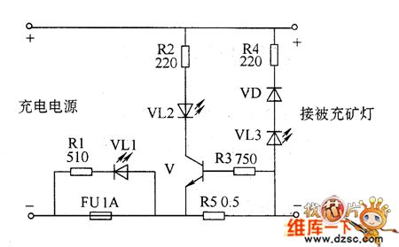
Mining charging indicator circuit consists of the resistors R1 ~ R5, light-emitting diode Ⅴ and fuse FU, and the circuit is shown as the chart. When the battery is charging, V is turned on, VL2 is lit. When the polarity connection of batteries is right, VL3 does not shine. If the battery polarity is reversed, the VL3 will be lit and emit yellow warning signal. When the fuse FU is fused because of some reasons (such as the internal battery short circuit), VL1 is lit. R1 ~ R4 select 1/4W metal film resistors; R5 uses 2 \ 7 wirewound resistor. VD selects 1N4007 silicon rectifier diode. VL1 ~ VL3 select φ5mm high-brightness light emitting diodes. V uses 58050 silicon NPN transistor.
(View)
View full Circuit Diagram | Comments | Reading(2019)
Motor protector circuit diagarm 3
Published:2011/6/2 3:38:00 Author:Lucas | Keyword: Motor protector

Motor protector circuit is composed of the power circuit, current detection circuit and protection control circuit, and the circuit is shown as the chart. Power supply circuit is composed of the power transformer T, bridge rectifier UR, filter capacitor C5, and the current limiting resistor R3 and regulator diode VS. Current detection circuit is composed of the current transformer TA, diode VD1, capacitor C1 and potentiometers RP1, RP2. Protection control circuit is composed of the time base control circuit IC IC, resistors R1, R2, diode VD2, capacitors C2 ~ C4, AC contactor K and relay KM. S1 is the stop button, S2 is the start button. R1 and R2 select 1/4W carbon film resistors; R3 uses 1W metal film resistor. RP1 uses WHW sealed membrane variable resistor; RP2 uses WSW organic solid variable resistor.
(View)
View full Circuit Diagram | Comments | Reading(778)
Hazardous area alarm circuit diagram 1
Published:2011/6/2 3:44:00 Author:Lucas | Keyword: Hazardous area , alarm

The voltage-stabilizing circuit is composed of three-terminal voltage regulator integrated circuit IC2, resistor R3, zener diode VS and filter capacitors C1, C2. Pyroelectric infrared detecting trigger circuit is composed of the pyroelectric infrared detection module IC1, transistors V1, V2, resistors R1, R2 and potentiometer RP. Electronic switch circuit consists of the electronic switch IC IC5, resistors R9, R10 and capacitor C8. Audio power amplifier consists of the power amplifier integrated circuit IC4, resistors R6 ~ R8, capacitors C4 ~ C7 and speaker BL. Low-frequency oscillator circuit consists of the time-base integrated circuit IC6, resistors R11, R12 and capacitors C9, C10 and other components.
(View)
View full Circuit Diagram | Comments | Reading(663)
Xunda elevator QKS9/10 three-phase AC door-opening circuit
Published:2011/6/2 1:06:00 Author:TaoXi | Keyword: Xunda, elevator, three-phase, AC, door-opening
Xunda elevator QKS9/10 three-phase AC door-opening circuit (View)
View full Circuit Diagram | Comments | Reading(479)
| Pages:1821/2234 At 2018211822182318241825182618271828182918301831183218331834183518361837183818391840Under 20 |
Circuit Categories
power supply circuit
Amplifier Circuit
Basic Circuit
LED and Light Circuit
Sensor Circuit
Signal Processing
Electrical Equipment Circuit
Control Circuit
Remote Control Circuit
A/D-D/A Converter Circuit
Audio Circuit
Measuring and Test Circuit
Communication Circuit
Computer-Related Circuit
555 Circuit
Automotive Circuit
Repairing Circuit