Basic Circuit
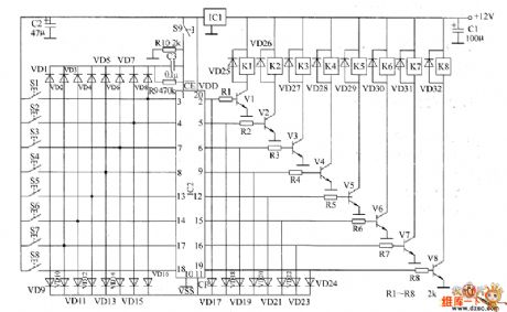
Eight-way lock electronic switch circuit diagram
Published:2011/6/1 7:00:00 Author:Lucas | Keyword: Eight-way , lock electronic switch | From:SeekIC

The 8-way lock electronic switch circuit is composed of the regulator filter circuit, input control circuit, latch circuit and control implementation circuit, and the circuit is shown as the chart. Regulator filter circuit is composed of the three terminal voltage regulator integrated circuit IC1 and filter capacitors C1, C2. Input control circuit consists of the control buttons S1 ~ S8, diodes VD1 ~ VD16. Latch circuit consists of eight D flip-flop integrated circuits IC2 and reset button S9, resistors R9 and R10, capacitor C3. Control implementation circuit is composed of the transistors V1 ~ V8, diodes VD17 ~ VD32, resistors R1 ~ R8 and relays K1 ~ K8. R1 ~ R10 uses 1/4W carbon film resistors or metal film resistors.
Reprinted Url Of This Article:
http://www.seekic.com/circuit_diagram/Basic_Circuit/Eight_way_lock_electronic_switch_circuit_diagram.html
Print this Page | Comments | Reading(3)

Article Categories
power supply circuit
Amplifier Circuit
Basic Circuit
LED and Light Circuit
Sensor Circuit
Signal Processing
Electrical Equipment Circuit
Control Circuit
Remote Control Circuit
A/D-D/A Converter Circuit
Audio Circuit
Measuring and Test Circuit
Communication Circuit
Computer-Related Circuit
555 Circuit
Automotive Circuit
Repairing Circuit
Code: