Circuit Diagram
Index 1829
Single channel wireless remote control transceiver circuit
Published:2011/5/30 1:47:00 Author:Christina | Keyword: Single channel, wireless, remote control, transceiver

The Single channel wireless remote control transceiver circuit is as shown:
(View)
View full Circuit Diagram | Comments | Reading(1549)
M17 movement protection circuit
Published:2011/5/30 1:52:00 Author:Christina | Keyword: movement, protection
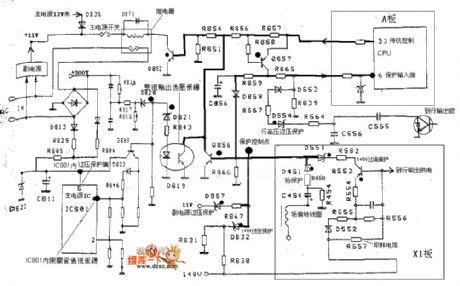

The M17 movement protection circuit is as shown:
(View)
View full Circuit Diagram | Comments | Reading(457)
multistage amplifier circuit
Published:2011/5/30 2:16:00 Author:Christina | Keyword: multistage, amplifier circuit

1. Coupling modes of the multistage amplifier circuit
In practice we always use three kinds of coupling modes: the resistance capacitance coupling, the direct coupling and the transformer coupling.
(1). Resistance capacitance coupling
It's connection method: connect the preamplifier output to the rear-amplifier output through the resistance and the capacitance.
It's features: the quiescent operating points of the stages are independent and easy to adjust.
It's weak point: can not amplify and change the slow signal and do not easy to integrate. The figure 1 shows the resistance capacitance coupling connection.
(2). Direct coupling
In order to avoid the influence of the capacitance to the slowly changing signal, we connect the two stages of amplifier circuits together, this is the direct coupling.
It's features: it can amplify the AC signal and the DC signal, easy to integrate, but it has the zero drift phenomenon.
Figure: multistage amplifier circuit (View)
View full Circuit Diagram | Comments | Reading(1253)
Angell water dispenser circuit
Published:2011/5/30 2:26:00 Author:Christina | Keyword: Angell, water dispenser
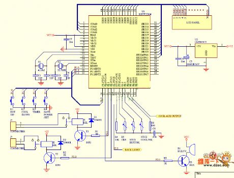
The Angell water dispenser circuit is as shown:
(View)
View full Circuit Diagram | Comments | Reading(2004)
Ultrasonic wave blindman road finder circuit
Published:2011/5/30 3:44:00 Author:Christina | Keyword: Ultrasonic wave, blindman, road finder
The Ultrasonic wave blindman road finder circuit is as shown in the figure (a); the Ultrasonic probe installation circuit is as shown in figure (b). (View)
View full Circuit Diagram | Comments | Reading(500)
555 Bootstrap Voltage Sawtooth Wave Generator Circuit
Published:2011/5/19 17:57:00 Author:Robert | Keyword: Bootstrap Voltage, Sawtooth Wave, Generator

As shown, the sawtooth generator is made up by the 555 monostable timing circuit and feedback bootstrap circuit.
The IC2 (LM741) operational amplifier is used as feedback bootstrap circuit. The 6 foot's output voltage would supply the sawtooth voltage's charging current for C1 through R1. The current size depends on the voltage regulator tube DW's clamp size and the resistance value of R1, which would change the sawtooth's cycle time and oscillation amplitude.
(View)
View full Circuit Diagram | Comments | Reading(2433)
Fan Circuit
Published:2011/5/20 9:44:00 Author:Robert | Keyword: Fan

The fan circuit is shown below. Using the LED to decorate the fan, itwould becolorful, unique. When the power is connected, the light would cross along the arc. The picture (a) uses 220V commercial power and its working current would be about 10mA. The picture (b) is flash light circuit and the power is directly from the electric motor connector end.
(View)
View full Circuit Diagram | Comments | Reading(465)
Photoelectric Control Circuit
Published:2011/5/21 0:45:00 Author:Robert | Keyword: Photoelectric, Control

In this circuit, IC1 is a optocoupler. When the LED is lighting, the phototransistor would be connected to trigger the SCR TIC206D connected. So this would contact and connect the large power AC load. The AC electricity would be added on the regulator D2, D3 and C1 through R, D1's voltage step-down and rectifier. Then it produces 30V DC voltage. T1, T2 and T3 are zero-crossing detection circuit. When the AC commercial power cross the zero stage it would trigger the SCR tobegin the soft-starting process.
(View)
View full Circuit Diagram | Comments | Reading(780)
Instrument Amplifier (INA101) Circuit With Eliminating AC Noise
Published:2011/5/19 8:10:00 Author:Robert | Keyword: Instrument Amplifier, Eliminating, AC, Noise

The instrument amplifier (INA101) circuit with eliminating AC noise is shown in the picture below. The amplification stage A1, A2 in the picture are chosen to use the integrated amplifier INA101, and the back stage A3 is chosen to use INA105. Also it uses the INA105 to make up the circuit like the feedbacl connection. So this would limit the power's AC noise.
(View)
View full Circuit Diagram | Comments | Reading(637)
Reducing Power Consumption ISO113 Circuit
Published:2011/5/21 1:56:00 Author:Robert | Keyword: Reducing, Power Consumption

The Reducing Power Consumption ISO113 Circuit is shown in the picture shown below. For single-channel or multi-channel synchronization application it requires the Vcc1's current to be less than +/-15mA. It can use a oscillation circuit to generator TTL voltage level to drive the synchronization input port(3 foot) and enable port (1 foot) to reduce the power consumption.
(View)
View full Circuit Diagram | Comments | Reading(503)
INA166 Low-Noise Low-Distortion Instrument Amplifier Pin Circuit
Published:2011/5/21 21:22:00 Author:Robert | Keyword: Low-Noise, Low-Distortion, Instrument, Amplifier, Pin

The INA166 is a low-noise, low-distortion instrument amplifier. The design of current feedback circuit makes it have a wide bandwidth and excellent dynamic response in a wide gain rang. The INA166 can be used in amplification of weak signals, such as miniature microphone (mike) and the amplification of underwater sound measurement device.Many industrial, instrument and medical applications also profit from its low noise and wide bandwidth. And its special distortion elimination circuit can reduce the distortion to very low level. With 200Ω source resistance the INA166 provides the low-noise performance which is almost close to the theoretical value.
(View)
View full Circuit Diagram | Comments | Reading(473)
TTS-200 Series Temperature-Control Thyristor Basic Application Circuit
Published:2011/5/21 20:25:00 Author:Robert | Keyword: Temperature-Control, Thyristor, Application

The temperature-control thyristor basic application circuit is shown in the picture below. RcA is the resistance to control the switch temperature. With different value of RcA it can get different switch temperature. The VD is working voltage. When the temperature is lower than the switch temperature, the temperature-control thyristor is disconnected and the Vo port outputs low voltage level. When the temperature is equal or higher than the switch temperature, the temperature-control thyristor is connected and Vo port outputs high voltage level. It should note that, the working voltage VD also has relations with switch temperature. To assure the stability of the switch temperature, VD should be taken measures of regulating voltage. C is a capacitor to prevent the disturbance.
(View)
View full Circuit Diagram | Comments | Reading(659)
sunshading board circuit
Published:2011/5/30 1:29:00 Author:Christina | Keyword: sunshading board
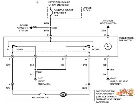
The sunshading board circuit is as shown:
(View)
View full Circuit Diagram | Comments | Reading(486)
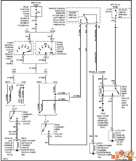
Buick trunk, back door and accelerator circuit
Published:2011/5/29 9:05:00 Author:Christina | Keyword: Buick, trunk, back door, accelerator
View full Circuit Diagram | Comments | Reading(392)
(Hitachi) CMT2998 protection circuit
Published:2011/5/29 8:44:00 Author:Christina | Keyword: Hitachi, protection circuit
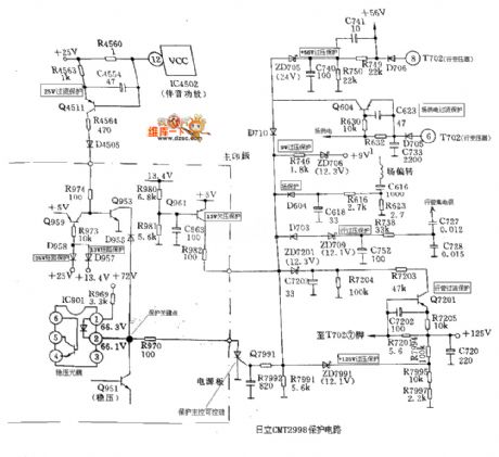
The (Hitachi) CMT2998 protection circuit is as shown in the figure:
(View)
View full Circuit Diagram | Comments | Reading(524)
Air condition remote controller circuit
Published:2011/5/30 3:18:00 Author:Christina | Keyword: Air condition, remote controller

The Air condition remote controller circuit is as shown:
(View)
View full Circuit Diagram | Comments | Reading(656)
Transistors EMB11, UMB11N, EMB2, UMB2N internal circuits
Published:2011/5/30 2:59:00 Author:Christina | Keyword: Transistors, internal circuits
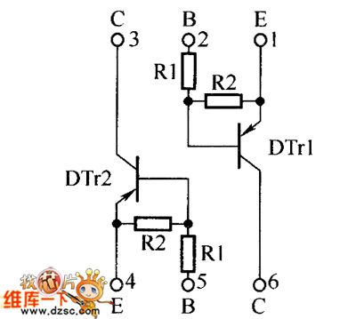
The Transistors EMB11, UMB11N, EMB2, UMB2N internal circuits are as shown:
(View)
View full Circuit Diagram | Comments | Reading(371)
JVCAV-S33 power supply protection circuit
Published:2011/5/30 2:21:00 Author:Christina | Keyword: power supply, protection circuit

During normal working, the field output has enough pulse output, and the voltage which is rectified and filtered by the D451 and C451 conducts the D452, the Q425 cuts off, the Q452 has the high electrical level.
(View)
View full Circuit Diagram | Comments | Reading(600)
DOHER (DVD) power supply circuit
Published:2011/5/30 3:12:00 Author:Christina | Keyword: DOHER, DVD, power supply

The DOHER (DVD) power supply circuit is as shown:
(View)
View full Circuit Diagram | Comments | Reading(2655)
Bubugao VCD-AB115 switch power supply circuit
Published:2011/5/30 3:20:00 Author:Christina | Keyword: Bubugao, switch, power supply

The Bubugao VCD-AB115 switch power supply circuit is as shown:
(View)
View full Circuit Diagram | Comments | Reading(1027)
| Pages:1829/2234 At 2018211822182318241825182618271828182918301831183218331834183518361837183818391840Under 20 |
Circuit Categories
power supply circuit
Amplifier Circuit
Basic Circuit
LED and Light Circuit
Sensor Circuit
Signal Processing
Electrical Equipment Circuit
Control Circuit
Remote Control Circuit
A/D-D/A Converter Circuit
Audio Circuit
Measuring and Test Circuit
Communication Circuit
Computer-Related Circuit
555 Circuit
Automotive Circuit
Repairing Circuit
