
Circuit Diagram
Index 1839
Street light timing circuit
Published:2011/5/24 2:19:00 Author:John | Keyword: Street light

This circuit shows that light control timing lights can automatically open in the evening for several hours and automatically off afterwards.
When darkness comes, under the action of the photoelectric switch, BG4 conducts. And oscillator circuit constituted by IC1 lamp begins to vibrate with constant IC 3 output pulse. As charging time constant of C3 is large and the oscillation period of oscillation circuit is T < <R7C3, the voltage at the starting moment for C3 is 1/3Vcc. The number 3 output end of IC is in high power level. As a result, bidirectional thyristor SCR is triggered to turn on and both ends of bulb ZD is energized to light.
(View)
View full Circuit Diagram | Comments | Reading(1142)
SCR automatic constant current charger circuit
Published:2011/5/24 2:31:00 Author:John | Keyword: automatic constant current charger

Principle of the circuit is shown in the figure. When it starts to charge, the voltage on two ends of the battery is low. Such is not enough to turn the transistor VT on. Phase-shift circuit formed by RC is to provide trigger current for SCR. The angle of phase-shift is determined by the RP2. SCR deadlines at negative half-cycle moment. Therefore, SCR charges by utilizing the half-wave silicon controlled rectifier to the battery generator. RP2 can be adjusted to adjust the charge current. The maximum charge current is set by R1. Indicating light is string in the circuit to indicate charging status and charge current. R3 is to adjust the brightness of light.
(View)
View full Circuit Diagram | Comments | Reading(4067)
CIC2851AE rice cooker reactor circuit
Published:2011/5/24 1:23:00 Author:John | Keyword: rice cooker reactor
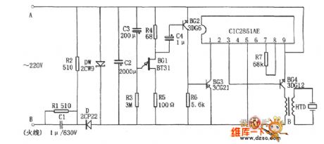
Rice cooker reactor circuit is shown in the figure. The circuit consists of 10-minute time delay circuit, 3V buck power supply, music integrated circuit CIC2851AE and piezoelectric ceramic HTD and so on. And the 10-minute delay circuit is mainly composited by BG1 R3 and C3. The 3V buck power supply mainly consist C1, R1, R2, D, DW and C2. The points A and B are parallel connected to control switch of the rice cooker.
When the rice cooker works normally, voltage on ends A and B is 0 and the entire circuit does not work. When water in rice cooker boils to dry, the master switch trips and ends A and B are given AC voltage. And the circuit begins to work. The voltage passes through the buck power supply and 10-minute delay circuit. After the delay circuit, the music integrated circuit CIC2851AE begins to work. And the output audio signal is amplified by the BG4 to drive HTD to be audible.
(View)
View full Circuit Diagram | Comments | Reading(958)
crystal diode DDZX7V5CTS internal circuit
Published:2011/5/24 0:59:00 Author:John | Keyword: crystal diode

Crystal diode DDZX7V5CTS internal circuit is shown below.
(View)
View full Circuit Diagram | Comments | Reading(551)
crystal diode DDZX8V2CTS internal circuit
Published:2011/5/24 0:58:00 Author:John | Keyword: crystal diode

Crystal diode DDZX8V2CTS internal circuit is shown below.
(View)
View full Circuit Diagram | Comments | Reading(518)
HW-03 rice cooker and porridge device circuit
Published:2011/5/24 0:57:00 Author:John | Keyword: rice cooker, porridge device
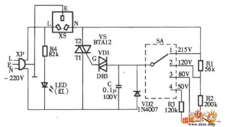
HW-03 rice cooker and porridge device circuit is shown below.
(View)
View full Circuit Diagram | Comments | Reading(2270)
Peugeot entire vehicle circuit
Published:2011/5/24 0:34:00 Author:John

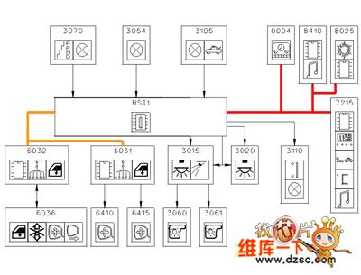
Peugeot entire vehicle circuit is shown below.
(View)
View full Circuit Diagram | Comments | Reading(591)
The power supply,stating, igniting, instrument and indicator circuit of Tianjin Xiali TJ7100 and 7100U
Published:2011/5/20 21:09:00 Author:Borg | Keyword: power supply, indicator, instrument
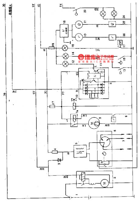
A,b,.c-fusible links; Fl-FI4-fuse; 1-battery; 2-starter; 3-separated diode; 4-additional resistance; 5-igniting coil(close flux); 6-electricity distributor; 7-spark piston; 7a-fan motor relay; 8-radiator fan motor; 9-temperature control switch; 10-oil cutting magnetic valve; 11-integral AC electricity generator; 12-charging indicator; 13-hand brake switch; 14-brake fluid level alarm indicator; 15-brake fluid switch; 16-oil pressure alarm lamp; 17-oil alarm switch; 18-pressure stabilizer (View)
View full Circuit Diagram | Comments | Reading(456)
The room lamp, wiper/washer,air-conditioning and radio circuit of Tianjin Xiali 7100 and 7100U
Published:2011/5/20 20:53:00 Author:Borg | Keyword: room lamp, wiper/washer, air-conditioning
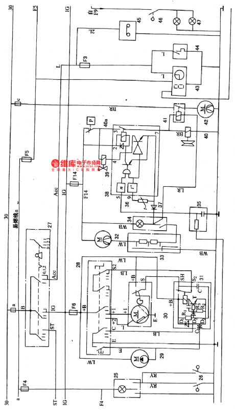
25-room lamp; 26-door control switch; 27-igniting switch; 28-wiper/washer switch(inside the combination switch); 29-washing motor; 30-wiper motor; 31-interval relay; 39-air-conditioning blow motor; 33-air blow transmission slipping switch; 34-air-conditioning switch; 35-engine steering signal filter; 36-thermistor; 37-diode; 38-air-conditioning control amplifier; 39-idling speed raising magnetic valve; 40-the magnetic clutch of air-conditioning compressor; 41a-pressure switch; 41-condenser fan motor relay; 42-condenser fan motor; 43-digital clock (View)
View full Circuit Diagram | Comments | Reading(893)
The engine fault codes of Daewoo Racer
Published:2011/5/21 22:23:00 Author:Borg | Keyword: fault codes, Daewoo Racer
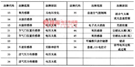
When the igniting switch is ON , short-connect the terminals, A and B, of the general detection outlet X1, so the fault code can be got if the fast repairing motor indicator flashes, then check the following table and find out the meaning and the cause of the code; if we want to remove the code, just cut off the igniting switch after dealing with the fault, and take down the fuse FI and install back in 10 seconds. The fault codes of Daewoo-Racer are seen in Table 5. The engine fault codes of Daewoo-Race
(View)
View full Circuit Diagram | Comments | Reading(1203)
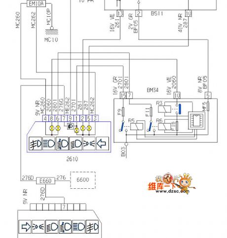
The cigarette lighter and room lamp circuit of Daewoo Racer
Published:2011/5/21 21:30:00 Author:Borg | Keyword: cigarette lighter, room lamp, Daewoo Racer

(6)cigarette lighter, clock, room lamp and seat belt(see as Figure 8)Under the fuse F13(20a), there are glove box lamp(E26), cigarette lighter(R1) and clock(H1), cigarette lighter lamp(E27) and ashtray light(E28). The engine chamber lamp(E29) still connects with the No.58 circuit and it is under the control of the light switch(S4).The room lamp(E30) and trunk lamp(E31) connect with the fuse of F15(20A)(see as Figure 9), and they are under the control of their own switch(hand or mechanic control, such as the door control switchs of S13 and S14). We can see in Figure 8 that when the igniting switch is on, and the seatbelt is not fixed, the switch of S1 will be on.
(View)
View full Circuit Diagram | Comments | Reading(992)
The lighting and brake lamp circuit of Daewoo Racer
Published:2011/5/21 22:00:00 Author:Borg | Keyword: lighting and brake lamp, Daewoo Racer

2.brake signal lamp(see as 6)The brake signal lamps (El5~E18) are under the control of brake switch (S7). If there is a A/T device, then it is the cutting/closing switch(S3) that take control, when the brake signal lamps are lighting, the magnetic valve(Y4) coil of the fluid torque converter is cut off simultaneously, then the power transmission is halted.
(View)
View full Circuit Diagram | Comments | Reading(601)
The rear window defroster, wiper and washer circuit of Daewoo Racer
Published:2011/5/21 21:12:00 Author:Borg | Keyword: rear window defroster, wiper/washer, Daewoo Racer
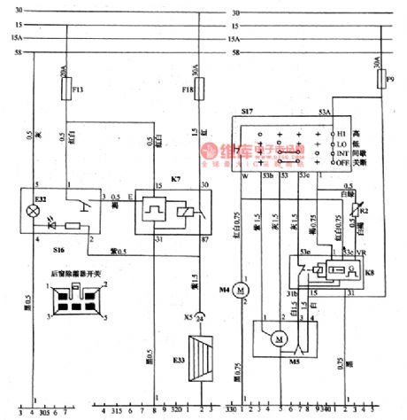
(7)wiper/washer system (see as Figure 10) When it is at the low speed gear(LO), the 53A-53 contact of wiper switch S17 is on, and the speed of the wiper arms is 30~45 times/min. When it is at the high speed gear (HI), the 53A-53b contact of the switch S17 is on, and the speed of the wiper arm is 60~70 times/min. When it is at the interval gear(INT), the 53A-I of the switch S17 is on, an 53-53e is also on, the interval relay (K8) takes action to cut off the normally closed contact(53e-53b), and the normally open contact (53e-15)is on, then the wiper motor(M5) is working at 1 gear, it wipes back and forth once and keep still for 4-21s, the interval time can be regulated by the control switch of R2.
(View)
View full Circuit Diagram | Comments | Reading(998)
The electric window circuit of Daewoo Racer
Published:2011/5/21 20:55:00 Author:Borg | Keyword: electric window, Daewoo Racer

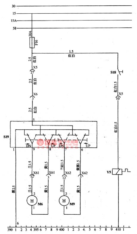
(9) the electric glass elevator(see as Figure 11a and 11b)It is a elevating motor which controls all the glass window by the combination switch of S19, the combination switch forms a circuit by 4 lever switches, the it can engage power brake and it links with the ground connection.
(View)
View full Circuit Diagram | Comments | Reading(1281)
The central door lock, radio and antenna circuit of Daewoo Racer
Published:2011/5/21 3:38:00 Author:Borg | Keyword: central door lock, Daewoo Racer
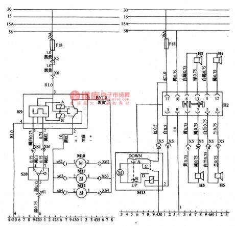
The central control door lock is controlled by keys(from outside) or handle(from inside) cf the driver door lock. When it is at the unlock position, the relay A closes. And the head-left, head-right,rear-left and rear-right door lock motors of M10,M11 and M12 rotate right at the same time, then the four doors open simultaneously. When S20 is at the lock position, the relay B closes , and the four motors rotate reversely, then the 4 doors are locked, so that it avoids the trouble of opening door one by one.
(View)
View full Circuit Diagram | Comments | Reading(1622)
The igniting circuit of Daewoo
Published:2011/5/21 3:50:00 Author:Borg | Keyword: igniting circuit
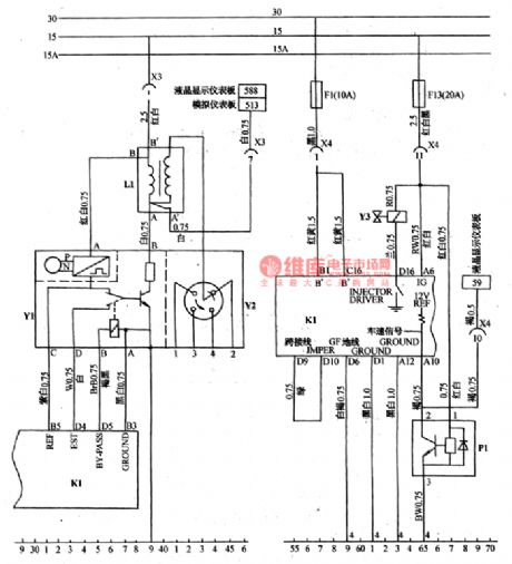
The igniting signal generator, igniting module Y1 and high voltage distributor compose into an integration. The resistance of the signal coil is 500~1500Ω, and the insulating resistance is infinitely large, the elementary - terminal connects with rotating speed meter.The elementary resistance ranges 0.25~0.45Ω, the secondary is 7.5~9.5KΩ, insulating resistance is infinite. The igniting sequence is 1-3-4-2, the points of testing electricity distributor is shown as Figure 2.
(View)
View full Circuit Diagram | Comments | Reading(667)
The photocoupler and its application circuit
Published:2011/5/21 4:52:00 Author:Borg | Keyword: photocoupler, application circuit


The photocoupler is a semiconductor photoelectric device which has been developed in recent years. Due to its little size, long lifespan, good anti-jamming function, wide working temperature range and total separation of input and output without touch, etc, it is widely used in electronic technology area and industrial automation control, besides, it can replace relays, transformers and wave chopper, so it could be used in separation circuits, switch circuit, D/A shift, logic circuit, overcurrent protection, long line transmission and LEV distribution, etc.
(View)
View full Circuit Diagram | Comments | Reading(809)
The AC control circuit consisting of photocouplers
Published:2011/5/21 5:17:00 Author:Borg | Keyword: AC control circuit, photocouplers

This is a AC control circuit consisting of photocouplers. The circuit is fixed with photocouplers, making the control circuit and the high voltage circuit separate the electric. The DC power supply of 5-24v/10mA controls the power of AC. When the AD voltage is over 0, VS2 gets through/cuts the line, therefore, when it is through, the current raising ratio of VS2 is low, so the high-frequency noise can be impeded. As the characters of load control are different, so the applied voltage source is not like the phase of VS2 current.
(View)
View full Circuit Diagram | Comments | Reading(880)
The application circuit of the photocoupler
Published:2011/5/21 4:30:00 Author:Borg | Keyword: application circuit, photocoupler

1.combination switch circuitIn the circuit of figure 1, when the input signal(ui) is a low LEV and the diode(V1) is stopped, the current of the LED in photocoupler BI is close to 0, the resistance between output terminals Q11 and Q12 is very high, which is equal to off ; the ui is a high LEV, vi is passable, the LED in BI is glowing, the resistance between Q11 and Q12 turns down, which is equal to on . As when ui is always a low LEV, the switch is off, so that it's often in high LEV state.
(View)
View full Circuit Diagram | Comments | Reading(592)
The fuse connection and control circuit of Daewoo Racer
Published:2011/5/21 20:45:00 Author:Borg | Keyword: fuse connection, control circuit, Daewoo Racer
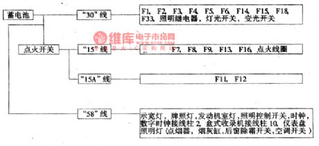
Figure 1b the relationship between each mainstream and the battery, igniting switch of Daewoo RacerThe igniting switch of S1 divides the car circuit into several mainstreams(see as Figure 1b and 1c): No.30 circuit links with the fire wire of the battery positive point; No.15 circuit, when the igniting switch is ON or ST , the fire wire is conducting, when it is OFF , the fire wire is not conducting; No.15 circuit is conducting when the igniting switch is ON , but not conducting when the switch is ST ; No.30 is passable only when the igniting switch is ST . (View)
View full Circuit Diagram | Comments | Reading(630)
| Pages:1839/2234 At 2018211822182318241825182618271828182918301831183218331834183518361837183818391840Under 20 |
Circuit Categories
power supply circuit
Amplifier Circuit
Basic Circuit
LED and Light Circuit
Sensor Circuit
Signal Processing
Electrical Equipment Circuit
Control Circuit
Remote Control Circuit
A/D-D/A Converter Circuit
Audio Circuit
Measuring and Test Circuit
Communication Circuit
Computer-Related Circuit
555 Circuit
Automotive Circuit
Repairing Circuit