
Circuit Diagram
Index 1840
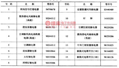
The positions of the relay and fuse on the central connection box of Daewoo Racer
Published:2011/5/22 0:34:00 Author:Borg | Keyword: central connection box, Daewoo Racer
There are two types of car bodies of Daewoo: the concave and the convex. The car equipment weighs 935kg(hand transmission) or 965kg(auto transmission), and the permitted weights are 1420kg and 1435kg. The max speeds are 165kg and 157kg. The model of the engine is Cl5CFOHC, and the engine is a 4-cylinder in-line water cooling throttle injection(single jet) engine, the diameter is 76.5mm, piston stroke is 8105mm, emission is 1498ml, compression ratio is 9.0, max power is 65.44kW/5500rpm, the maximum torque is 126.4N.m/30Orpm, it started by e-ignition, igniting advance angle is 10°(idling speed is 700±5Orpm).
(View)
View full Circuit Diagram | Comments | Reading(1547)
The light and signal wiring circuit of DPCA-VOLCANE DC7140 ZX(1)
Published:2011/5/19 20:21:00 Author:Borg | Keyword: wiring circuit, DPCA-VOLCANE

The light switch(211) is not on at the 0 gear, the license lights(391,392), left-head right-head position lamps(422,493, width lamp), left-rear right-rear lamps(496,497), and position indicator, which are under F13 and F12, are got through at 1 gear.
20-loudspeaker; 35-battery; 40-instrument board; 50-power supply box; 52-inscribed fuse box; 62-ground connection box; 130-alarm for light not-off; 170-steering flash; 391,392-left and right license lamp; 480,481-left and right tail lamp; 482-485-left-head, right-head, right-rear and left-rear fog lamp; 587,588-head and rear fog switch. (View)
View full Circuit Diagram | Comments | Reading(538)
The power supply and starter circuit of Daewoo Racer
Published:2011/5/22 0:14:00 Author:Borg | Keyword: power supply, Daewoo Racer

Figure 1c The power supply and staring circuit of Daewoo RacerG1-battery; G2-AC generator; M1-starter; S1-igniting switch; S2-neutral gear switch; F1(10A):the ECM terminals(B1,C16) of generator e-controller; F2(10A):the width lamp and instrument lamp linked by No.58 circuit; F3(10A):the head high beam(left); F4(10A):the head high beam(right). High beam indicator.F5(10A):the head low beam(left); F6(10A):the head low beam(right); F14(30A):the fan relay of radiator(high speed and low speed). (View)
View full Circuit Diagram | Comments | Reading(1274)
555 fatigue degree tester circuit
Published:2011/5/24 1:53:00 Author:TaoXi | Keyword: fatigue, degree, tester circuit

As the figure 16-26 shows, the astable multivibrator is composed of the 555 and R1,R2,RP1,C1, the oscillation frequency f=1.44/(R1+RP1+2R2)C1.
The principle of the fatigue degree tester is based on the visual eye temporarily leave phenomenon of human eyes. The average person under the normal conditions, the eyes can sense the continuous light with the frequency of 30~40Hz. When you are fatigue or drinking too much, the perception frequency will reduce. The figure parameter's oscillation frequency is about 20~60Hz, you can adjust the RP1 to make the frequency of 35Hz, when you are fatigue, the LED will start flashing.
(View)
View full Circuit Diagram | Comments | Reading(664)
555 pulse electrotherapy instrument circuit
Published:2011/5/24 2:20:00 Author:TaoXi | Keyword: pulse, electrotherapy, instrument
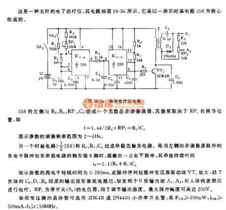
This is one kind of no needle electronic instrument, the circuit is as shown in figure 16-34, it uses a double time base circuit 556 as the core.
The astable multivibrator is composed of the left part of 556 and the R2,R3,RP1,C1, the oscillation frequency depends on the RP1's adjusting position, f=1.44/(R2+RP1+R3)C1.
Another time base circuit (1/2 556) and the R6,R7,C4 constitute the monostable trigger circuit. The figure parameter's high electrical level duration is 0.295ms. This pulse sequence is amplified by the pulse transformer driver stage VT1, and gets through the output waveform rectifier circuit which is composed of the C6,D1,R8, at last it adds to the two pieces of slice shape output stages A1 and A2.
(View)
View full Circuit Diagram | Comments | Reading(1205)
555 simple electronic massager circuit
Published:2011/5/25 1:22:00 Author:TaoXi | Keyword: simple, electronic massager
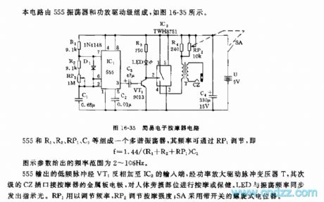
This circuit is composed of the 555 oscillator and the amplifier driving stage, as the figure 16-25 shows.
The multivibrator is composed of the 555 and R1, R2, RP1, C1, the frequency can be adjusted by RP1, f=1.44/(R1+R2+RP1)C1. The figure parameter's frequency range is 2 to 106Hz.
The low frequency pulse of 555 is reversed by VT1, and it adds to IC2's input port, then it is amplified by the power tube to drive the pulse transformer T, the subprime CZ socket connects to the metal plate electrode of massager to massage the human body strain parts. The RP1 can be used to adjust the frequency, the RP2 can be used to adjust the massage strength, SA uses the spiral potentiometer with the switch.
(View)
View full Circuit Diagram | Comments | Reading(2206)
555 simulation breathing technique information instrument circuit
Published:2011/5/24 2:35:00 Author:TaoXi | Keyword: simulation, breathing technique, information instrument
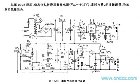
As the figure 16-25 shows, the information instrument is composed of the step-down rectifying power supply (VDD=+12V), the timing circuit, the multivibrator, the amplifier function output head.
The start timing circuit is composed of the IC1 and R1,RP1,C3, the timing time td=1.1(R1+RP1)C3. In the timing time, J closes to control the connection of J1-1,J1-2's contact points.
The controllable multivibrator is composed of the IC2 and R5, R6, RP2, C8, f=1.44/(R5+2R6+RP2)C8, you can change the frequency with the control voltage of pin-5 (RP3). VT1 uses the VMOS FET power transistor. The function output head uses the 0.85um gallium arsenide semiconductor laser, the PTC special infrared radiation ceramic material and the strong magnetic field SmCo magnet.
(View)
View full Circuit Diagram | Comments | Reading(826)
555 blind person electronic guide audio circuit
Published:2011/5/24 2:50:00 Author:TaoXi | Keyword: blind person, electronic, guide, audio circuit
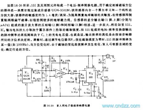
As the figure 16-30 shows, the voltage-frequency conversion circuit is composed of the 555 and the surrounding components, the device that can be used to determine the direction of the earth's magnetic field is one piece of Hall effect integrated sensor UGN-3501M, this sensor has a Hall unit and a linear differential amplifier, the sensitivity of this device is about 1.4 mV/gauss, in order to improve the sensitivity, we add two roots of flat magnetic bar on both sides of the sensor. The size of the IC2 output voltage depends on the magnetic field intensity of the Hall device, the output impulse frequency of the voltage-frequency converter which is composed of 555 depends on the charging voltage value of C2.
(View)
View full Circuit Diagram | Comments | Reading(927)
555 smoking prohibition language warning circuit
Published:2011/5/24 3:21:00 Author:TaoXi | Keyword: smoking, prohibition, language warning
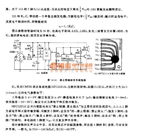
The monostable trigger circuit is composed of the 555 circuit and the R2,C1, when this circuit is triggered by the low electrical level (1/3VDD), it outputs the high electrical level, the high-level maintenance time td=1.1R2C1.
The IC2 uses the CMOS language integrated circuit HFC5221A, the soft package structure is as shown in figure (b), the shape dimension is 24mm x 14mm, it's electrical parameters are:
The operating voltage is 2.4V~5V, the rated voltage is 4.4V; the quiescent current is lower than 1uA, the output port driving current is 3~6mA, the using temperature is -10℃~60℃, the trigger mode is the high electrical level and positive pulse trigger.
(View)
View full Circuit Diagram | Comments | Reading(597)
The auto gain-control circuit of photocoupler
Published:2011/5/21 20:25:00 Author:Borg | Keyword: auto gain-control, photocoupler

This is a auto gain control circuit of photocoupler, which is mainly consists of AC amplifiers and rectifier circuits. Suppose that we put a AC signal on the non-inverting input terminal of AI, if the input signal is lower than the set value, after it was output by A1 and rectified by A2, the current which go across the LED of MCD521 is minor, so the resistance of the light dependent resistor (LDR) in MCD521 is higher than R1. Therefore, the maximum of total resistance is 30OkΩ(the resistance of RI), and the gain of AI becomes the largest.
(View)
View full Circuit Diagram | Comments | Reading(1521)
The luminous flux adjustment equipment circuit of light dependent resistors (LDR)
Published:2011/5/23 3:55:00 Author:Borg | Keyword: luminous flux, adjustment equipment circuit, light dependent resistors

This is a luminous flux adjustment equipment circuit of light dependent resistors (LDR). This circuit is used to measure the luminous flux on the LDR, and adjusts it. If the luminous flux is growing, then the resistance of RG is decreasing, and the base LEV of VT1 and VT2 is rising, finally, VT1 is conducting and VT2 is blocked. At the moment, as VT1 and VT2 are Schmidt circuits, therefore, VT3 becomes conducting. Then the relay of KI takes action and its terminal of KI-I links with the power supply, and the motor runs, the silt is adjusted to make the luminous diminish. When the luminous flux reaches the regulated value, VTI is blocked and the motor stops running.
(View)
View full Circuit Diagram | Comments | Reading(1264)
Multivibrator circuit
Published:2011/5/23 20:49:00 Author:John | Keyword: Multivibrator
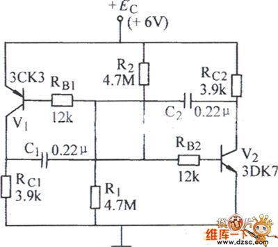
Multivibrator circuit is shown below.
(View)
View full Circuit Diagram | Comments | Reading(539)
Minimal light intensity light control switch circuit
Published:2011/5/23 20:47:00 Author:John | Keyword: light control switch

In the situation with minimal light intensity, it is not appropriate to use photosensitive photodiode resistor or general photodiode. It is advised to use dedicated photodiode BPX63 with minimal cut-off current.
In the circuit, the light irradiates on diode D1 continuously. If switches S1 and S2 both close, the photocurrent results in short circuit. At this time, FET T1 and T2 and the resistors R1 and R2 constitute the source emitter follower. When the switch S2 closes, the output of operational amplifier is connected to the input of the anti-body of same phase through the field-effect transistor. If the switches S1 and S2 both open, the strong negative feedback circuit cuts off. But the operating point of field-effect transistor T2 changes.
(View)
View full Circuit Diagram | Comments | Reading(884)
Toyota Vios airbag control circuit
Published:2011/5/23 20:15:00 Author:John | Keyword: airbag

Toyota Vios airbag control circuit is shown below.
(View)
View full Circuit Diagram | Comments | Reading(2193)
fan cycling speed control circuit
Published:2011/5/23 20:09:00 Author:John | Keyword: fan
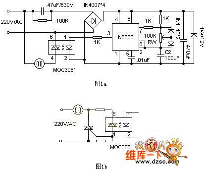
The circuit is shown in Figure 1a. NE555 in the circuit is connected as a square wave generator with an adjustable duty cycle. It can change the duty cycle through adjusting RW. When the pin 3 of the NE555 outputs in high power level, primary end of the zero-off-type optocoupler MOC3061 achieves forward current of about 10mA. And it leads the internal infrared emitting diode of gallium silicide to emit infrared light. The two-way switch in photosensitive zero-crossing detector opens when the electricity over zero. Then the power supply of the fan motor is connected. And the fan runs for air supply. When the pin 3 in the NE555 outputs in low power level, two-way switch turns off and the fan stops.
(View)
View full Circuit Diagram | Comments | Reading(1835)
Multi-function wireless remote control fan with TWH923619238 circuit
Published:2011/5/19 20:09:00 Author:John | Keyword: wireless remote control fan
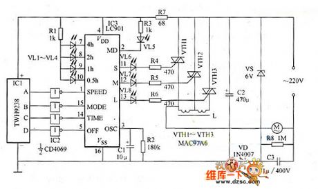
This example describes a wireless remote control fan speed controller, which is constituted by a 4 way remote control module and a fan speed control integrated circuit. It can transform an ordinary fan into a wireless remote control multi-functional speed fan.
The circuit for the receive part of the wireless remote control speed fan is shown in Figure 1. The transmitter is a four way TWH9236 key chain style transmitter. The button A of the transmitter is used for speed regulation and the button B is used for the wind mode regulation. Besides, the key C key is used for time setting and key D is for turning off the device.
(View)
View full Circuit Diagram | Comments | Reading(3022)
Battery thermocouple protection circuit
Published:2011/5/19 0:42:00 Author:John | Keyword: thermocouple

K-type thermocouple is placed in insulation terminal block and the ambient temperature of the thermocouple is continuously controlled by 1N914 diode. Diode voltage can modify Thermal EMF on the junction force through feedback of small voltage regulator. Thermal EMF would be sent through to amplifier by 1.5MΩ and 475Ω. During the calibration, the thermocouple junction should be placed in the freezing cold water. Adjust 500Ω to ensure the output pressure of zero. Then insert thermocouple into the 250 ℃ furnace and adjust range for the output of 2.50V. In the range of 0 ~ 250 ℃, the accuracy for the K-type thermocouple is ± 3 ℃.
(View)
View full Circuit Diagram | Comments | Reading(2888)
light control flash safety lights circuit
Published:2011/5/15 2:26:00 Author:John | Keyword: safety light

This circuit applies to safety lights in the construction site.
At the construction site, the two points A and B is put in the grid. The electricity of 220V is stepped-down by transformer B and the diode D1. Afterwards, the electricity passes through rectifier DW and filter C1 filter. Then, the DC electricity of 9V is provided to a photoelectric switch. DW affects well as a dual role of a rectifier and a regulator. During the day under strong light, photoelectric switch blocks. SCR1 has no trigger current, being in the off state. And the red signal ZD light does not shine. When in the night, photoelectric switch is in the on state. The oscillator circuit composed by IC and other components opens to work. Ultra-low frequency rectangular pulse is output by the IC constantly. SCR2 opens under this high pulse conduction and closes in the low level. As a result, the twinkling lights can be seen.
(View)
View full Circuit Diagram | Comments | Reading(550)
Agricultural Automatic Water Feeder (4)
Published:2011/5/22 19:44:00 Author:Sue | Keyword: Agricultural Automatic Water Feeder

When there is no water, V1,V2,V4 are disconnected, and K is connected. M begins to feed water and VL is illuminated.
When the level reaches B, V1 has high level and V2 has low level. M continues to feed water.
When the level reaches A, V4 has high level. V3 is disconnected and K is released. VL goes out and M stops working.
When the level is lower than A, V4 is disconnected and V3 is disconnected. K and KM don’t work. When the level is lower than B, V1 V2 are disconnected and VL is illuminated. M begins to feed water. (View)
View full Circuit Diagram | Comments | Reading(707)
Agricultural Automatic Water Feeder (2)
Published:2011/5/22 19:34:00 Author:Sue | Keyword: Agricultural, Automatic, Water Feeder

When the level is low, VT is triggered to be connected and K1 is connected. HL2 is illuminated and M begins to feed water.
When the level is becoming higher, VT is still connected. When the level reaches a certain level, K2 is connected and K1 is released. VT is disconnected. HL2 goes out and M stops feeding water.
When the level is lower, K1 and KM are disconnected. When the level reaches SA1, VT is connected again and M begins to feed water again. (View)
View full Circuit Diagram | Comments | Reading(548)
| Pages:1840/2234 At 2018211822182318241825182618271828182918301831183218331834183518361837183818391840Under 20 |
Circuit Categories
power supply circuit
Amplifier Circuit
Basic Circuit
LED and Light Circuit
Sensor Circuit
Signal Processing
Electrical Equipment Circuit
Control Circuit
Remote Control Circuit
A/D-D/A Converter Circuit
Audio Circuit
Measuring and Test Circuit
Communication Circuit
Computer-Related Circuit
555 Circuit
Automotive Circuit
Repairing Circuit