Signal Processing
fan cycling speed control circuit
Published:2011/5/23 20:09:00 Author:John | Keyword: fan | From:SeekIC

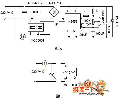
The circuit is shown in Figure 1a. NE555 in the circuit is connected as a square wave generator with an adjustable duty cycle. It can change the duty cycle through adjusting RW. When the pin 3 of the NE555 outputs in high power level, primary end of the zero-off-type optocoupler MOC3061 achieves forward current of about 10mA. And it leads the internal infrared emitting diode of gallium silicide to emit infrared light. The two-way switch in photosensitive zero-crossing detector opens when the electricity over zero. Then the power supply of the fan motor is connected. And the fan runs for air supply. When the pin 3 in the NE555 outputs in low power level, two-way switch turns off and the fan stops.
Reprinted Url Of This Article:
http://www.seekic.com/circuit_diagram/Signal_Processing/fan_cycling_speed_control_circuit.html
Print this Page | Comments | Reading(3)

Article Categories
power supply circuit
Amplifier Circuit
Basic Circuit
LED and Light Circuit
Sensor Circuit
Signal Processing
Electrical Equipment Circuit
Control Circuit
Remote Control Circuit
A/D-D/A Converter Circuit
Audio Circuit
Measuring and Test Circuit
Communication Circuit
Computer-Related Circuit
555 Circuit
Automotive Circuit
Repairing Circuit
Code: