Signal Processing
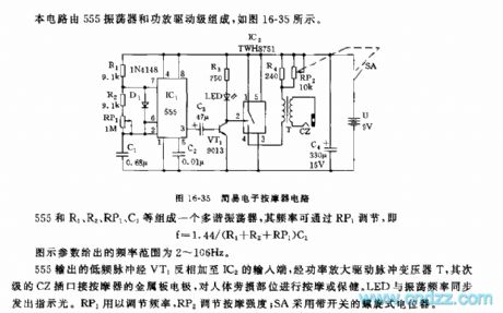
555 simple electronic massager circuit
Published:2011/5/25 1:22:00 Author:TaoXi | Keyword: simple, electronic massager | From:SeekIC

This circuit is composed of the 555 oscillator and the amplifier driving stage, as the figure 16-25 shows.
The multivibrator is composed of the 555 and R1, R2, RP1, C1, the frequency can be adjusted by RP1, f=1.44/(R1+R2+RP1)C1. The figure parameter's frequency range is 2 to 106Hz.
The low frequency pulse of 555 is reversed by VT1, and it adds to IC2's input port, then it is amplified by the power tube to drive the pulse transformer T, the subprime CZ socket connects to the metal plate electrode of massager to massage the human body strain parts. The RP1 can be used to adjust the frequency, the RP2 can be used to adjust the massage strength, SA uses the spiral potentiometer with the switch.
Reprinted Url Of This Article:
http://www.seekic.com/circuit_diagram/Signal_Processing/555_simple_electronic_massager_circuit.html
Print this Page | Comments | Reading(3)

Article Categories
power supply circuit
Amplifier Circuit
Basic Circuit
LED and Light Circuit
Sensor Circuit
Signal Processing
Electrical Equipment Circuit
Control Circuit
Remote Control Circuit
A/D-D/A Converter Circuit
Audio Circuit
Measuring and Test Circuit
Communication Circuit
Computer-Related Circuit
555 Circuit
Automotive Circuit
Repairing Circuit
Code: