
Circuit Diagram
Index 1832
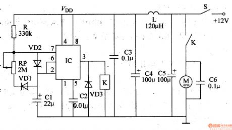
Car Windshield Wiper Controller (the 2nd)
Published:2011/5/20 2:54:00 Author:Felicity | Keyword: Car Windshield Wiper Controller (the 2nd)
Work of the circuit
The circuit consists of Multivibrator, control circuit and filtering circuit (It is showed in picture 7-164.).
Turn on the switch S +12v voltage supplies IC with working power. When the Multivibrator is working the pulse signal is outputted from pin 3. When the signal is of high level the motor M starts to work. When the signal is of low level the motor stops working. (View)
View full Circuit Diagram | Comments | Reading(549)
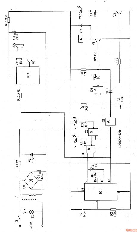
Eye-care Lamps (the 2nd)
Published:2011/5/20 1:51:00 Author:Felicity | Keyword: Eye-care Lamps (the 2nd)
Work of the circuit
The circuit consists of power circuit, timer, light examine circuit, LED shining circuit, light control circuit and music circuit (It is showed in picture 9-69.).
Turn on the power and the timer begins to work. Lamp EL is lightened but either music circuit or HA works. When the regular time is over EL stops working and HA sends out music to remind the user to have a rest.
Change the value of RP to change the sensitivity of light-dependent control. (View)
View full Circuit Diagram | Comments | Reading(463)
Bell of the Bicycle (the 2nd)
Published:2011/5/20 1:42:00 Author:Felicity | Keyword: Bell of the Bicycle (the 2nd)

Work of the circuit
The circuit consists of voice circuit and voice-frequency amplifying circuit (It is showed in picture 7-168.).
The +12V voltage which comes from storage battery separates into two parts. One of them supplies working power to IC2 while the other one supplies 3V DC voltage to IC1.
Press button S IC1 begins to work and voice signal is outputted from its O/P. The signal drives BL make the voice “Please give way, thank you” after being amplified. (View)
View full Circuit Diagram | Comments | Reading(551)
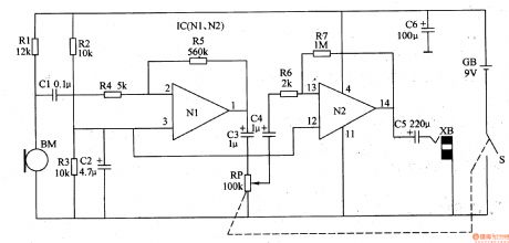
Hearing-aid (the 1st)
Published:2011/5/19 21:17:00 Author:Felicity | Keyword: Hearing-aid (the 1st),
Work of the circuit
The hearing-aid circuit consists of mike BM, volume potentiometer RP and two-step amplifier circuit (It is showed in picture 9-77.).
Sound signal is collected and translated into electric signal by mike BM. Then it is inputted into IC’s pin 2 through CI and R4 and outputted from pin 1 after being amplified by amplifier N1. At last it is returned to sound by earphone after being amplified by operating amplifier N2.
(View)
View full Circuit Diagram | Comments | Reading(3225)
F2-750A Intelligent fuzzy control rice cooker circuit
Published:2011/5/23 22:48:00 Author:John | Keyword: rice cooker
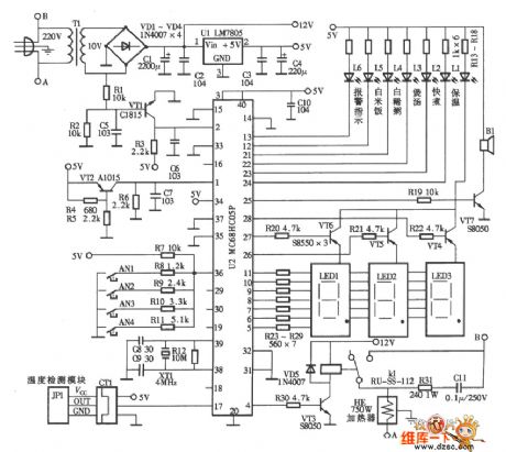
F2-750A Intelligent fuzzy control rice cooker circuit is shown below.
(View)
View full Circuit Diagram | Comments | Reading(944)
Quartz crystal oscillator circuit
Published:2011/5/23 23:23:00 Author:John | Keyword: Quartz crystal oscillator

Quartz crystal oscillator circuit is shown below.
(View)
View full Circuit Diagram | Comments | Reading(590)
Car amplifier circuit
Published:2011/5/27 7:14:00 Author:John | Keyword: Car amplifier

Car amplifier circuit is shown below.
(View)
View full Circuit Diagram | Comments | Reading(677)
Toyota Vios automatic transmission control circuit
Published:2011/5/23 21:50:00 Author:John | Keyword: automatic transmission

Toyota Vios automatic transmission control circuit is shown below.
(View)
View full Circuit Diagram | Comments | Reading(3249)
sensor transmission principle circuit
Published:2011/5/23 22:04:00 Author:John | Keyword: sensor transmission

RTD input connects the bypass capacitor to reduce or eliminate interference. The capacitor is connected to the pipe end 7. If the DC voltage on pin 7 is not zero, it can be considered that the pin 7 is terminated to the ground.
(View)
View full Circuit Diagram | Comments | Reading(493)
MB-YC50A Luxury type rice cooker circuit
Published:2011/5/23 22:31:00 Author:John | Keyword: Luxury type rice cooker

MB-YC50A Luxury type rice cooker circuit includes power supply board circuit ( figue a) and
computer control board circuit (firgue b).
(View)
View full Circuit Diagram | Comments | Reading(644)
SONY KV2184 switch power supply circuit
Published:2011/5/23 22:35:00 Author:John | Keyword: switch

SONY KV2184 switch power supply circuit is shown below.
(View)
View full Circuit Diagram | Comments | Reading(1486)
555 snore suppressor circuit
Published:2011/5/29 20:41:00 Author:TaoXi | Keyword: 555, snore, suppressor
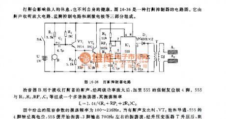
The figure 16-36 shows the snore suppressor circuit, it is composed of the snore receiving circuit, the monitoring control circuit and the stimulating circuit.
The pickup B can be used to receive the snore, the snore is amplified by the two stages power tube, then it adds to the mandatory resetting port pin-4. The multivibrator is composed of the 555 and R5,R6,RP1,C3, the oscillation frequency f=1.44/(R5+RP1+2R6)C3.
The RC parameters' oscillation frequency is 100~236Hz. When there is the snore, VT2 conducts, pin-4 of 555 has the high electric potential, the 555 starts working, pin-3 outputs the 700Hz oscillating wave, and this oscillating wave is boosted by the pressurization transformer T to stimulate both ends of the electrode DJ to produce the 45V electrical pulse.
(View)
View full Circuit Diagram | Comments | Reading(548)
555 simple electrocardiogram validator circuit
Published:2011/5/25 2:18:00 Author:TaoXi | Keyword: 555, simple, electrocardiogram, validator
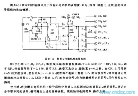
The figure 16-15 shows the validator that can be used to check the sensitivity, the damping, the linearity, the difference distinguishing ratio, the paper passing speed and the guide line connection of the electrocardiogram validator.
The astable multivibrator is composed of the IC(555) ad RP1, R1, RP2, C1, the T=0.693(RP1+RP2+R1)C1. By adjusting RP1, the oscillation period T=0.6 second, and you can change the duty ratio by adjusting RP2, then the pulse width will be 0.2 second. You can get the 4mV square wave signal from CK3. This square wave signal is separated by R4~R7, so each resistance has the square wave signal of 1 mV. You can get out the 1.5V square wave signal from the LED as the difference ratio measurement signal to set the electrocardiogram device.
(View)
View full Circuit Diagram | Comments | Reading(409)
555 simple electric acupuncture anesthesia instrument circuit
Published:2011/5/25 1:48:00 Author:TaoXi | Keyword: 555, simple, electric, acupuncture, anesthesia, instrument

As the figure 16-16 shows, the electric acupuncture anesthesia instrument is composed of the pulse signal source, the trigger circuit and the driving circuit.
The astable multivibrator is composed of the 555 and R1,RP1,C1~C3, the oscillation frequency depends on the charging and discharging time constant of the circuit, f=1.44/(R1+RP1)C. By changing the position of the switch K, you can change of oscillation frequency, also you can adjust the frequency by adjusting the RP1.
IC2 uses the sound control integrated circuit SK-III , it is composed of the amplification shaping circuit, the frequency selection circuit, the trigger circuit and the driving circuit, in this circuit, the SK-III is used as the trigger.
(View)
View full Circuit Diagram | Comments | Reading(3117)
Emitter follower reference circuit
Published:2011/5/26 2:30:00 Author:Christina | Keyword: Emitter follower, reference circuit

The Emitter follower reference circuit
(View)
View full Circuit Diagram | Comments | Reading(707)
crystal diode DDZX9700TS circuit
Published:2011/5/28 0:28:00 Author:chopper | Keyword: crystal diode
View full Circuit Diagram | Comments | Reading(395)
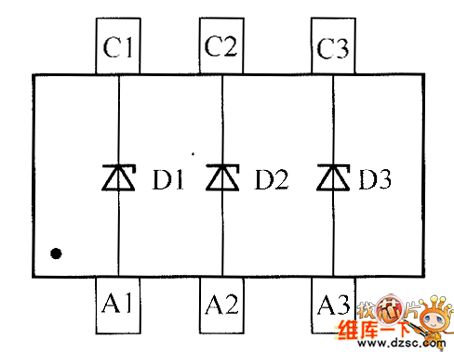
crystal diode DDZX9702TS internal circuit
Published:2011/5/29 7:39:00 Author:chopper | Keyword: crystal diode, internal

View full Circuit Diagram | Comments | Reading(339)
crystal diode DDZX9703TS internal circuit
Published:2011/5/29 7:21:00 Author:chopper | Keyword: crystal diode, internal

View full Circuit Diagram | Comments | Reading(347)
crystal diode DDZX9707TS internal circuit
Published:2011/5/29 6:59:00 Author:chopper | Keyword: crystal diode, internal

View full Circuit Diagram | Comments | Reading(348)
crystal diode DDZX9711TS internal circuit
Published:2011/5/29 22:09:00 Author:chopper | Keyword: crystal diode, internal

View full Circuit Diagram | Comments | Reading(481)
| Pages:1832/2234 At 2018211822182318241825182618271828182918301831183218331834183518361837183818391840Under 20 |
Circuit Categories
power supply circuit
Amplifier Circuit
Basic Circuit
LED and Light Circuit
Sensor Circuit
Signal Processing
Electrical Equipment Circuit
Control Circuit
Remote Control Circuit
A/D-D/A Converter Circuit
Audio Circuit
Measuring and Test Circuit
Communication Circuit
Computer-Related Circuit
555 Circuit
Automotive Circuit
Repairing Circuit