
Circuit Diagram
Index 1825
555 electric rice cooker automatic power regulator circuit
Published:2011/6/1 19:21:00 Author:TaoXi | Keyword: 555, electric rice cooker, automatic, power regulator

As the figure 15-30 shows, the regulator is composed of the step-down rectifier circuit (VDD=13V), the oscillation control circuit and the silicon controlled phase shifting trigger circuit.
When the switch K is at the strong fire position, the VT2 cuts off, the contact point J1-1 is in the NC connection state, at this time R1 is in parallel with the RP1 and R2, and the RC trigger network is composed of the R1 and C1, after the SCR is conducted, the socket can get the 220V voltage. When the water is boiled, you dial the switch K to the mini fire position, the temperature sensor VT1 (3AX31) is in the heat conduction state, the pin-2 of 555 has the low electrical level, so the 555 sets, pin-3 has the high electrical level, VT2 conducts, J closes and J1-1 releases.
(View)
View full Circuit Diagram | Comments | Reading(1401)
800W three-port two-way SCR light-reducing circuit
Published:2011/5/29 8:42:00 Author:Christina | Keyword: 800W, three-port, two-way, SCR, light-reducing

The MBS4991 two-way SCR switch is produced by the Motorola company, you can control the three-port two-way SCR by using it. The 1MΩ resistance can change the three-port two-way SCR's angle of flow from 0°to 170°. When the angle of flow is maximum, the power that adds to the load can be more than 97% of the full power. No matter which position the tone potentiometer is, the first half cycle's angle of flow is the same as the rear half cycle's.
(View)
View full Circuit Diagram | Comments | Reading(959)
Internal circuit of the crystal transistors EMB6 and UMB6N
Published:2011/5/26 8:24:00 Author:Christina | Keyword: Internal circuit, crystal transistors
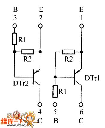
The Internal circuit of the crystal transistors EMB6 and UMB6N is as shown:
(View)
View full Circuit Diagram | Comments | Reading(532)
Shining type logic pen circuit (CD4069) composed of the gate circuit
Published:2011/5/26 6:54:00 Author:Christina | Keyword: Shining type, logic pen, gate circuit
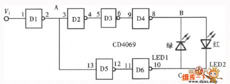
The logic pen also called the logic detection probe, it is the common tool to detect the various point's logical state of the digital circuit. The digital circuit has three kinds of logical state: the high electrical level 1 , the low electrical level 0 and the high resistance state . The test result of the logical state can be displayed by the LED and the sounder, also you can use the digital led to display it. The logic detection pen which is composed of the six inverter CD4069 and the LED is as shown in the figure.
(View)
View full Circuit Diagram | Comments | Reading(842)
Strip graphics display circuit
Published:2011/5/26 2:50:00 Author:Christina | Keyword: Strip, graphics, display circuit
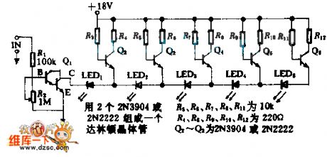
The transistor Q2~Q3 control the LED1~LED5 as the rise strip display of the input voltage. If you adjust the R2, the voltage minimum change range is 0.1~0.5V, the increment of the five LEDs is 0.1V; the voltage maximum change range is 1~10V, the increment is 1V. The input resistance of the circuit is more than 100KΩ.
(View)
View full Circuit Diagram | Comments | Reading(650)
Logarithmic operation circuit
Published:2011/5/26 2:45:00 Author:Christina | Keyword: Logarithmic, operation

The logarithmic operation circuit makes the output voltage and the input voltage present the logarithm function. We replace the Rf of the inverse proportion circuit with the diode or the transistor to form the logarithmic operation circuit. The circuit is as shown:
(View)
View full Circuit Diagram | Comments | Reading(504)
Recorder remote display circuit
Published:2011/5/25 20:50:00 Author:Christina | Keyword: Recorder, remote display

The CC4082 connects into the positive feedback, and trigger is composed of the CC4082 and the bar function switch to guarantee the output electrical signals has no jitter. The or door or the trigger simulates the operating logic of the recorder to make the six LEDs respectively indicate the states of recording, playing, tape rewinding, FF, stop and the pause.
The CC4013 drives the light-emitting diode directly, the current limiting is 4 to 5mA. You can choose the Q port to drive the LED, the purpose is the Q port and the logic stance is irrelevant. If the output current reduces when it is over-driving, it will not influence the logical state of Q.
(View)
View full Circuit Diagram | Comments | Reading(614)
TDA1521 single power supply supplying application circuit
Published:2011/5/25 19:05:00 Author:Christina | Keyword: single power supply, supplying, application circuit

Figure: TDA1521 single power supply supplying application circuit
(View)
View full Circuit Diagram | Comments | Reading(702)
PID control circuit
Published:2011/5/25 21:35:00 Author:Christina | Keyword: PID, control circuit

The PID control circuit is as shown, it is the proportion (P), integral (I) and the differential (D) control circuit. The proportion circuit which is composed of A1 is related with the loop gain, by adjusting RP1, you can change the inverter gain in the range of 0.5 to ∞; it is also the integral circuit, the integral time constant can be changed in the range of 22 to 426S; A3 is the differential circuit, the time constant is decided by the Cl(Rl+R(RP3)); A4 outputs the proportion, integral and differential circuits to the phase inversion to compose the U.
(View)
View full Circuit Diagram | Comments | Reading(8820)
Limit reminding spiral circuit composed of sixty LEDs
Published:2011/5/20 2:18:00 Author:Christina | Keyword: Limit reminding, spiral circuit, sixty LEDs

The sixty LEDs are arranged in spiral form on the display board; the connecting line connects to two 4017 ICs with the matrix form. So when the IC2 and IC1 count respectively, every light emitting diode turns on as the permutation order. The IC3 is the square wave oscillator, the frequency depends on the R2 and C1's values, the output of it is used as the IC1's clock, when IC1's count is 10, it will output a carry output as the IC2's clock. When the count is 60, IC1 and IC2 are all reset to zero, the new cycle starts. Both two integrated circuits have the limited flow function.
(View)
View full Circuit Diagram | Comments | Reading(2842)
133MHz multi-channel output clock pulse driving circuit
Published:2011/5/19 20:45:00 Author:Christina | Keyword: 133MHz, multi-channel, output clock, pulse driving circuit
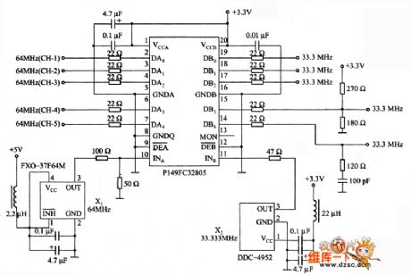
The 133MHz multi-channel output clock pulse driving circuit is as shown. It uses the clock pulse driving circuit which is composed of the P149FC32805, the maximum clock frequency is 133 MHz, and it can be used to distribute the base board internal clock signal. Output delay time is less than 270ps for synchronous management.
(View)
View full Circuit Diagram | Comments | Reading(644)
Multifunctional Motor Protector (4)
Published:2011/5/25 6:28:00 Author:Sue | Keyword: Multifunctional, Motor, Protector

When the triphase alternating current power is working well, A's potential is 0V.
The protection circuit consists of RV4,RV5,R4,R5,KN,Q,FU,KM,S and M.
When any phase of the triphase alternating current power has an abnormal voltage, the public terminal's potential will be higher. KN's inside circuit will be connected. KM's coil will be short and KM is released. The power will be cut off to protect the motor. (View)
View full Circuit Diagram | Comments | Reading(466)
Character display type logic pen circuit (CD4011) composed of the gate circuit (2)
Published:2011/5/26 7:36:00 Author:Christina | Keyword: Character display, logic pen, gate circuit
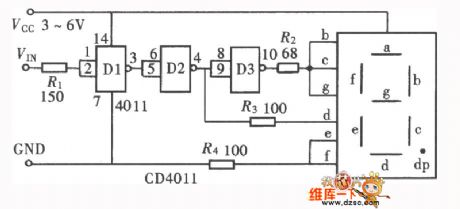
The character display type logic pen which is composed of the gate circuit has various forms, it can be composed by the inverter or the NAND gate, and also the NOR gate. The logic pen in the figure is composed of the NAND gate CD4011 and the common anode digital tube.
(View)
View full Circuit Diagram | Comments | Reading(1899)
Character display type logic pen circuit (CD4069) composed of the gate circuit (3)
Published:2011/5/26 7:38:00 Author:Christina | Keyword: Character display, logic pen, gate circuit
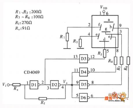
The Character display type logic pen circuit (CD4069) composed of the gate circuit (3) is as shown:
(View)
View full Circuit Diagram | Comments | Reading(954)
Character display type logic pen circuit (CD4001) composed of the gate circuit (4)
Published:2011/5/26 7:42:00 Author:Christina | Keyword: Character display, logic pen, gate circuit
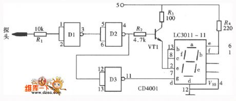
The Character display type logic pen circuit (CD4001) composed of the gate circuit (4):
(View)
View full Circuit Diagram | Comments | Reading(2069)
Special breeding temperature control and sea wave sound circuit
Published:2011/5/26 7:49:00 Author:Christina | Keyword: breeding temperature, sea wave, sound circuit

As the figure shows, it is composed of the temperature sensing device, the comparison circuit, the silicon-controlled rectifier control cooling circuit, the sea wave sound circuit and the AC step-down rectifier circuit.etc. This circuit has some points of features such as the wide temperature control range, the high control accuracy and the circuit is simple, practical.
(View)
View full Circuit Diagram | Comments | Reading(840)
AD7520 "burr" phenomenon overcoming interface circuit
Published:2011/5/26 7:51:00 Author:Christina | Keyword: "burr" phenomenon, overcoming, interface circuit
View full Circuit Diagram | Comments | Reading(679)
Open-circuit state display logic pen circuit (CD4001) (1)
Published:2011/5/26 8:03:00 Author:Christina | Keyword: Open-circuit state, display, logic pen
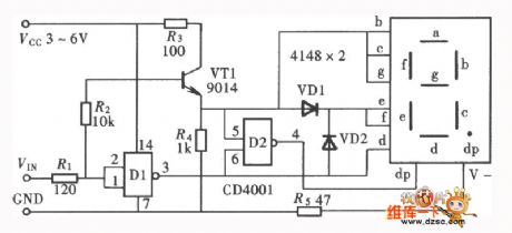
The figure shows the logic pen that can test and display the high and low electrical level and the open-circuit state.
(View)
View full Circuit Diagram | Comments | Reading(1880)
DAC811 right aligned data format address searching circuit connection diagram
Published:2011/5/26 8:11:00 Author:Christina | Keyword: right aligned, data format, address, searching, connection diagram
View full Circuit Diagram | Comments | Reading(699)
ML15L movement protection circuit
Published:2011/5/26 8:12:00 Author:Christina | Keyword: movement, protection

The ML15L movement protection circuit is as shown:
(View)
View full Circuit Diagram | Comments | Reading(647)
| Pages:1825/2234 At 2018211822182318241825182618271828182918301831183218331834183518361837183818391840Under 20 |
Circuit Categories
power supply circuit
Amplifier Circuit
Basic Circuit
LED and Light Circuit
Sensor Circuit
Signal Processing
Electrical Equipment Circuit
Control Circuit
Remote Control Circuit
A/D-D/A Converter Circuit
Audio Circuit
Measuring and Test Circuit
Communication Circuit
Computer-Related Circuit
555 Circuit
Automotive Circuit
Repairing Circuit

