Basic Circuit
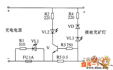
Mining charging indicator circuit diagram
Published:2011/6/2 4:04:00 Author:Lucas | Keyword: Mining , charging indicator | From:SeekIC

Mining charging indicator circuit consists of the resistors R1 ~ R5, light-emitting diode Ⅴ and fuse FU, and the circuit is shown as the chart. When the battery is charging, V is turned on, VL2 is lit. When the polarity connection of batteries is right, VL3 does not shine. If the battery polarity is reversed, the VL3 will be lit and emit yellow warning signal. When the fuse FU is fused because of some reasons (such as the internal battery short circuit), VL1 is lit. R1 ~ R4 select 1/4W metal film resistors; R5 uses 2 \ 7 wirewound resistor. VD selects 1N4007 silicon rectifier diode. VL1 ~ VL3 select φ5mm high-brightness light emitting diodes. V uses 58050 silicon NPN transistor.
Reprinted Url Of This Article:
http://www.seekic.com/circuit_diagram/Basic_Circuit/Mining_charging_indicator_circuit_diagram.html
Print this Page | Comments | Reading(3)

Article Categories
power supply circuit
Amplifier Circuit
Basic Circuit
LED and Light Circuit
Sensor Circuit
Signal Processing
Electrical Equipment Circuit
Control Circuit
Remote Control Circuit
A/D-D/A Converter Circuit
Audio Circuit
Measuring and Test Circuit
Communication Circuit
Computer-Related Circuit
555 Circuit
Automotive Circuit
Repairing Circuit
Code: