Basic Circuit
555 multi-function appliance socket circuit (1)
Published:2011/6/1 3:06:00 Author:TaoXi | Keyword: 555, multi-function, appliance, socket | From:SeekIC

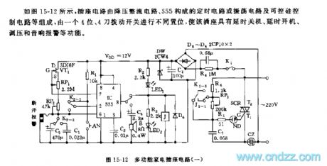
As the figure 15-12 shows, the socket circuit is composed of the step-down rectifier circuit, the timing circuit or oscilation circuit which is composed of the 555, and the silicon-controlled rectifier control circuit.etc, this circuit is set by a 4-bit, 4 knives switch, this socket has the function of delay shutdown, delay starting up, voltage adjustment and sound alarm.
The step-down rectifier circuit supplies the voltage of VDD=+12V to the controller. If you cut off K1 and dial down the K2-3, then adjust RP3, so you can adjust the conduction angle of the SCR and adjust the output voltage.
The 555 and R4,RP1,RP2,C3,C4,VT1 can form the timing boot or timing shutdown circuit, also they form the constant-current source recharging Much harmonic oscillator and the sound alarm circuit.
Reprinted Url Of This Article:
http://www.seekic.com/circuit_diagram/Basic_Circuit/555_multi_function_appliance_socket_circuit_1.html
Print this Page | Comments | Reading(3)

Article Categories
power supply circuit
Amplifier Circuit
Basic Circuit
LED and Light Circuit
Sensor Circuit
Signal Processing
Electrical Equipment Circuit
Control Circuit
Remote Control Circuit
A/D-D/A Converter Circuit
Audio Circuit
Measuring and Test Circuit
Communication Circuit
Computer-Related Circuit
555 Circuit
Automotive Circuit
Repairing Circuit
Code: