Basic Circuit
555 multi-function appliance socket circuit (2)
Published:2011/6/1 3:27:00 Author:TaoXi | Keyword: 555, multi-function, appliance, socket | From:SeekIC

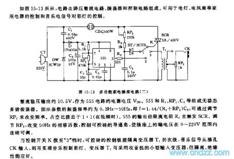
As the figure 15-13 shows, the circuit is composed of the step-down rectifier circuit, the oscillator and the control circuit. This circuit can be used in wide range of applications such as the electric lamp control, the electric fan control and the color lights control.
The rectifier voltage stabilization output is about 10.5V, this output can be used as the 555 circuit's power supply voltage VDD. The astable multivibrator is composed of the 555 and R1, RP1, C3. The figure parameters' oscillation frequency is about 0.3Hz~50Hz, f=1.44/(R1+RP1)C3, you can change the frequency by adjusting the RP1. The duty ratio is about 1:1. The output of 555 triggers the SCR through the current limiting resistor R2. By adjusting RP2 and changing the 50Hz phase shift factors, you can control the conduction angle of the SCR to make the terminal voltage in the range of 0~220V.
Reprinted Url Of This Article:
http://www.seekic.com/circuit_diagram/Basic_Circuit/555_multi_function_appliance_socket_circuit_2.html
Print this Page | Comments | Reading(3)

Article Categories
power supply circuit
Amplifier Circuit
Basic Circuit
LED and Light Circuit
Sensor Circuit
Signal Processing
Electrical Equipment Circuit
Control Circuit
Remote Control Circuit
A/D-D/A Converter Circuit
Audio Circuit
Measuring and Test Circuit
Communication Circuit
Computer-Related Circuit
555 Circuit
Automotive Circuit
Repairing Circuit
Code: