Basic Circuit
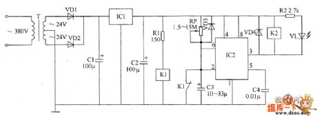
Time relay circuit diagram 2
Published:2011/5/21 0:07:00 Author:Lucas | Keyword: Time relay | From:SeekIC

The relay circuit is composed of the power supply circuit, monostable circuit and relay control circuit, the circuit is shown as the chart. Power circuit is composed of the power transformer T, rectifier diodes VD1, VD2, three-terminal voltage regulator integrated circuit IC1 and filter capacitors C1, C2. Monostable circuit is composed of the potentiometer RP, diode VD3, capacitors C3, C4, time-base integrated circuit IC2 and the normally closed contact of relay K1. Relay control circuit consists of resistors R1, R2, relays K1, K2, diode VD4 and light emitting diode VL. R1 uses 1/2W metal film resistor; R2 uses 1/4W metal film resistor. RP uses organic, solid variable resistor. C1 uses aluminium electrolytic capacitor with the voltage in 50 V; C2 and C3 select aluminium electrolytic capacitor with the voltage in 13 V; C4 uses monolithic capacitor or polyester capacitor.
Reprinted Url Of This Article:
http://www.seekic.com/circuit_diagram/Basic_Circuit/Time_relay_circuit_diagram_2.html
Print this Page | Comments | Reading(3)

Article Categories
power supply circuit
Amplifier Circuit
Basic Circuit
LED and Light Circuit
Sensor Circuit
Signal Processing
Electrical Equipment Circuit
Control Circuit
Remote Control Circuit
A/D-D/A Converter Circuit
Audio Circuit
Measuring and Test Circuit
Communication Circuit
Computer-Related Circuit
555 Circuit
Automotive Circuit
Repairing Circuit
Code: