© 2008-2012 SeekIC.com Corp.All Rights Reserved.
Basic Circuit
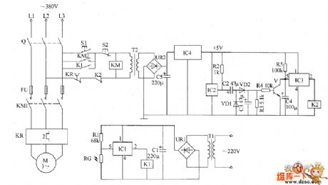
Warping machine automatic controlled economizer circuit diagram
Published:2011/5/21 23:51:00 Author:Lucas | Keyword: Warping machine , automatic controlled, economizer | From:SeekIC

The warping machine automatic controlled economizerircuit consists of the light control circuit, magnetic circuit, +5 V power supply circuit and motor main control circuit, the circuit is shown as the chart. Light control circuit consists of photoresistor RC, resistor R1, electronic switch integrated circuit IC1, relay K1, filter capacitor Cl, bridge rectifier UR1 and power transformer T1. Magnetic circuit is composed of the Hall sensor integrated circuit IC2, resistors R2 ~ R5, electronic switch integrated circuit IC3, capacitors C2 ~ C4, diodes VD1, VD2, transistor V and relays K2. +5 V power supply circuit is composed of the power transformer T2, bridge rectifier UR2, filter capacitor C5 and three-terminal voltage regulator integrated circuit IC4. The motor main control circuit consists of knife switch Q, start button S1, stop button S2, fuse FU, AC contactor KM and thermal relay KR.
Reprinted Url Of This Article:
http://www.seekic.com/circuit_diagram/Basic_Circuit/Warping_machine_automatic_controlled_economizer_circuit_diagram.html
Print this Page | Comments | Reading(3)

Article Categories
power supply circuit
Amplifier Circuit
Basic Circuit
LED and Light Circuit
Sensor Circuit
Signal Processing
Electrical Equipment Circuit
Control Circuit
Remote Control Circuit
A/D-D/A Converter Circuit
Audio Circuit
Measuring and Test Circuit
Communication Circuit
Computer-Related Circuit
555 Circuit
Automotive Circuit
Repairing Circuit
New published articles
Response in 12 hours

Code: