Basic Circuit
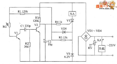
Optical proximity switch circuit diagram
Published:2011/5/22 0:06:00 Author:Lucas | Keyword: Optical, proximity switch | From:SeekIC

The optical proximity switch circuit consists of the photosensitive resistor RG, varistor RV, transistors V1 and V2, resistors R1 ~ R5, capacitors C1 and C2, voltage regulator diode VS, thyristor VT and diodes VD1 ~ VD5 etc. the circuit is shown as the chart. RV is the pressure sensitive resistor for protection to prevent the surge voltage shocks. During the turn-in VT, the 6V voltage on the VS can provide working power for the optical circuit by R7. R1 ~ R5 select 1/4W metal film resistors. RC uses the photosensitive resistor with light resistance being less than 20kΩ, the dark resistance being greater than 500kΩ . RV uses 270V varistor. C1 uses high-frequency ceramic capacitor or mica capacitor; C2 uses the aluminium electrolytic capacitor with the voltage in 16V. VD1 ~ VD5 use 1N4007 silicon rectifier diodes. VS selects 1N4735 (1W, 6.2V) silicon voltage regulator diode. V1 and V2 use 59013 silicon NPN transistor. VT uses MCR100-6 intergranular tube. KA uses intermediate relay with the coil voltage in DC 220V, and the current capacity on its contact should be based on rational power of load.
Reprinted Url Of This Article:
http://www.seekic.com/circuit_diagram/Basic_Circuit/Optical_proximity_switch_circuit_diagram.html
Print this Page | Comments | Reading(3)

Article Categories
power supply circuit
Amplifier Circuit
Basic Circuit
LED and Light Circuit
Sensor Circuit
Signal Processing
Electrical Equipment Circuit
Control Circuit
Remote Control Circuit
A/D-D/A Converter Circuit
Audio Circuit
Measuring and Test Circuit
Communication Circuit
Computer-Related Circuit
555 Circuit
Automotive Circuit
Repairing Circuit
Code: